Specification—2215A Service
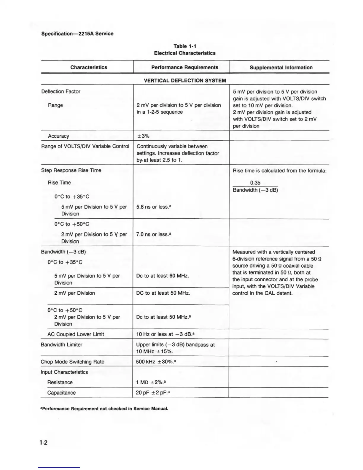
Table 1-1
Electrical Characteristics
Characteristics
Performance Requirements
Supplemental Information
VERTICAL DEFLECTION SYSTEM
Deflection Factor
Range
2 mV per division to 5 V per division
in a 1-2-5 sequence
5 mV per division to 5 V per division
gain is adjusted with VOLTS/DIV switch
set to 10 mV per division.
2 mV per division gain is adjusted
with VOLTS/DIV switch set to 2 mV
per division
Accuracy
±3%
Range of VOLTS/DIV Variable Control
Continuously variable between
settings. Increases deflection factor
by. at least 2.5 to 1.
Step Response Rise Time
Rise Time
0°C to +35°C
5 mV per Division to 5 V per
Division
5.8 ns or less.8
Rise time is calculated from the formula:
0.35
Bandwidth (—3 dB)
0°C to +50°O
2 mV per Division to 5 Y per
Division
7.0 ns or less.8
Bandwidth (-3 dB)
0°C to +35°C
5 mV per Division to 5 V per
Division
Dc to at least 60 MHz.
Measured with a vertically centered
6-division reference signal from a 50 Q
source driving a 50
U
coaxial cable
that is terminated in 50 J2, both at
the input connector and at the probe
input, with the VOLTS/DIV Variable
control in the CAL detent.
2 mV per Division
DC to at least 50 MHz.
0°C to +50°C
2 mV per Division to 5 V per
Division
Dc to at least 50 MHz.8
AC Coupled Lower Limit
10 Hz or less at —3 dB.8
Bandwidth Limiter Upper limits (—3 dB) bandpass at
10 MHz ±15%.
Chop Mode Switching Rate
500 kHz ± 30%.a
•
Input Characteristics
Resistance
1 MQ ± 2%.a
Capacitance
20 pF ±2 pF.8
■Performance Requirement not checked in Service Manual.
1-2