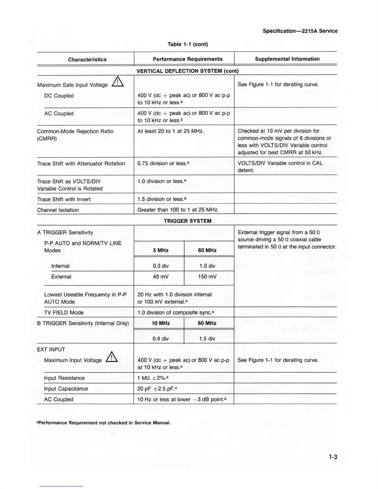
Table 1-1 (cont)
Specification—2215A Service
Characteristics
Performance Requirements
Supplemental Information
VERTICAL DEFLECTION SYSTEM (cont)
Maximum Safe Input Voltage A
See Figure 1-1 for derating curve.
DC Coupled
400 V (dc + peak ac) or 800 V ac p-p
to 10 kHz or less.3
AC Coupled
400 V (dc + peak ac) or 800 V ac p-p
to 10 kHz or less.3
Common-Mode Rejection Ratio
(CMRR)
At least 20 to 1 at 25 MHz.
Checked at 10 mV per division for
common-mode signals of 6 divisions or
less with VOLTS/DIV Variable control
adjusted for best CMRR at 50 kHz.
Trace Shift with Attenuator Rotation
0.75 division or less.3
VOLTS/DIV Variable control in CAL
detent.
Trace Shift as VOLTS/DIV
Variable Control is Rotated
1.0 division or less.3
Trace Shift with Invert
1.5 division or less.3
Channel Isolation
Greater than 100 to 1 at 25 MHz.
TRIGGER SYSTEM
A TRIGGER Sensitivity
P-P AUTO and NORM/TV LINE
Modes
Internal
External trigger signal from a 50 0
source driving a 50
Q
coaxial cable
terminated in 50 S2 at the input connector.
5 MHz 60 MHz
0.3 div
1.0 div
External 40 mV
150 mV
Lowest Useable Frequency in P-P
AUTO Mode
20 Hz with 1.0 division internal
or 100 mV external.3
TV FIELD Mode 1.0 division of composite sync.3
B TRIGGER Sensitivity (Internal Only)
10 MHz 60 MHz
0.4 div
1.5 div
EXT INPUT
Maximum Input Voltage / ' \
400 V (dc + peak ac) or 800 V ac p-p
at 10 kHz or less.3
See Figure 1-1 for derating curve.
Input Resistance 1 MSi ± 2%.3
Input Capacitance
20 pF ± 2.5 pF.a
AC Coupled
10 Hz or less at lower —3 dB point.3
1-3
“Performance Requirement not checked in Service Manual.