b. Set the calibration generator to produce a 20-mV
signal.
c. Set the bottom of the signal on the center horizontal
graticule line using the Channel 2 POSITION control.
d. Set the Channel 2 Input Coupling switch to AC.
e. CHECK— Display is centered about the center hori
zontal graticule line.
f. Move the cable from the CH 2 OR Y input connector to
the CH 1 OR X input connector. Set the VERTICAL MODE
switch to CH 1.
g. Repeat parts c through e using the Channel 1 controls.
h. Disconnect the test equipment from the instrument.
9. Adjust Attenuator Compensation (C12, C11, C5,
C4, C62, C61, C55, and C54)
a. Set:
VOLTS/DIV (both) 0.1 V
Input Coupling (both) DC
A SEC/DIV 20
ns
b. Connect the high-amplitude square wave output via a
50-S2 cable and a 50-li terminator to the CH 1 OR X input
connector.
c. Set the generator to produce a 10-kHz, 5-division
display.
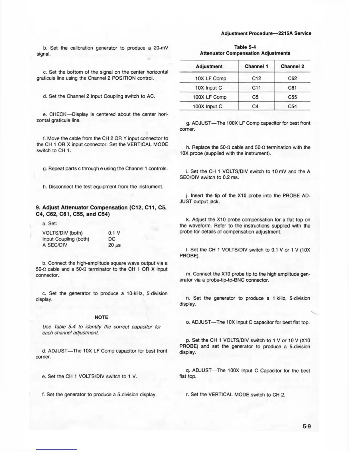
NOTE
Use Table 5-4 to identify the correct capacitor fo r
each channel adjustment.
d. ADJUST—The 10X LF Comp capacitor for best front
corner.
e. Set the CH 1 VOLTS/DIV switch to 1 V.
f. Set the generator to produce a 5-division display.
Adjustment Procedure—2215A Service
Table 5-4
Attenuator Compensation Adjustments
Adjustment Channel 1
Channel 2
10X LF Comp C12 C62
10X Input C C11
C61
100X LF Comp C5
C55
100X Input C
C4 C54
g. ADJUST—The 100X LF Comp capacitor for best front
corner.
h. Replace the 50-Q cable and 50-fi termination with the
10X probe (supplied with the instrument).
i. Set the CH 1 VOLTS/DIV switch to 10 mV and the A
SEC/DIV switch to 0.2 ms.
j. Insert the tip of the X I0 probe into the PROBE AD
JUST output jack.
k. Adjust the X I0 probe compensation for a flat top on
the waveform. Refer to the instructions supplied with the
probe for details of compensation adjustment.
I. Set the CH 1 VOLTS/DIV switch to 0.1 V or 1 V (1 OX
PROBE).
m. Connect the X I0 probe tip to the high amplitude gen
erator via a probe-tip-to-BNC connector.
n. Set the generator to produce a 1 kHz, 5-division
display.
v
o. ADJUST—The 10X Input C capacitor for best flat top.
p. Set the CH 1 VOLTS/DIV switch to 1 V or 10 V (XI0
PROBE) and set the generator to produce a 5-division
display.
q. ADJUST—The 100X Input C Capacitor for the best
flat top.
r. Set the VERTICAL MODE switch to CH 2.
5-9