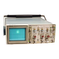
Adjustment Procedure—2215A Service
s. Repeat parts c through q for Channel 2.
t. Disconnect the test equipment from the instrument.
10. Check Alternation Operation
a. Set:
VERTICAL MODE
Input Coupling (both)
A and B SEC/DIV
A&B INT
BOTH and ALT
GND
50 ms
CH 1
12. Adjust High-Frequency Compensation (C237)
and Delay Line Compensation (R240 and R241)
a. Set:
VERTICAL MODE
BW LIMIT
VOLTS/DIV (both)
Input Coupling (both)
A SEC/DIV
A SOURCE
CH 1
Off (button out)
10 mV
DC
0.05
ns
INT
b. Connect the positive-going fast-rise square wave out
put via a 50-52 cable, a 10X attenuator, and a 50-52 termina
tion to the CH 1 OR X input connector.
b. Position the Channel 1 and Channel 2 traces about 2
divisions apart using the Channel 1 and Channel 2 POSI- c Set the generator to produce a 1-MHz, 5-division
TION controls. djSpiay.
c. CHECK—Sweeps alternate for all the A SEC/DIV
switch settings.
d. Set the top of the display to the center horizontal grati
cule line using the Channel 1 POSITION control.
e. ADJUST— HF Peak Comp (C237) for 2% overshoot
A t sweep speeds o f 2 ms per division or faster, the (0.1 division) on the displayed signal.
trace alternations occur too rapidly to be observed.
f. ADJUST— DL Comp 1 (R240) and DL Comp 2 (R241)
for best flat top on the front corner.
11. Check Chop Operation
a. Set:
BOTH and CHOP
1 ms
VERT MODE
EXT
VERTICAL MODE
A SEC/DIV
A&B INT
A SOURCE
g. Repeat parts e and f until no further improvement is
noted.
h. Set the CH 1 VOLTS/DIV switch to 5 mV.
b. Connect the 10X probe to the EXT INPUT connector.
i. Set the generator to produce a 5-division display.
c. Connect the 10X probe tip to TP537.
j. CHECK— Display peak-to-peak aberrations are within
±4% (0.2 division or less).
d. CHECK— Period of one complete square-wave cycle
is between 1.6 and 2.6 horizontal divisions.
e. Disconnect the 10X probe from TP537 and the EXT
INPUT connector.
f. CHECK—Two traces are visible for all A SEC/DIV
switch settings.
k. Repeat part j for each of the following CH 1
VOLTS/DIV switch settings: 5 mV through 0.5 V. Adjust the
generator output and add or remove the 10X attenuator as
necessary to maintain a 5-division display at each
VOLTS/DIV switch setting.
I. Move the cable from the CH 1 OR X input connector to
the CH 2 OR Y input connector. Set the VERTICAL MODE
switch to CH 2.
5-10

 Loading...