Adjustment Procedure—2215A Service
m. Set the CH 2 VOLTS/DIV switch to 5 mV.
n. Repeat parts i through k for Channel 2.
o. Disconnect the test equipment from the instrument.
NOTE
Install the instrument cabinet for the remaining vertical
checks and allow a 20-minute warm-up period before
continuing with the Adjustm ent Procedure. See the
“Cabinet" remove and replace instructions located in
the “Maintenance" section o f the manual.
13. Check Bandwidth Limit Operation
a. Set:
VERTICAL MODE CH 1
Vertical POSITION (both) Midrange
BW LIMIT On (button in)
VOLTS/DIV Variable (both) CAL detent
Input Coupling (both) DC
A SEC/DIV 20
ns
b. Connect the leveled sine-wave generator output via a
50-fi cable and a 50-fi termination to the CH 1 OR X input
connector.
c. Set the generator to produce a 50-kHz, 6-division
display.
d. Increase the generator output frequency until the dis
play amplitude decreases to 4.2 divisions.
e. CHECK—Generator output frequency is between
8.5 MHz and 11.5 MHz.
14. Check Bandwidth
a. Set:
BW LIMIT Off (button out)
VOLTS/DIV (both) 2 mV
b. Set the generator to produce a 50-kHz, 6-division
display.
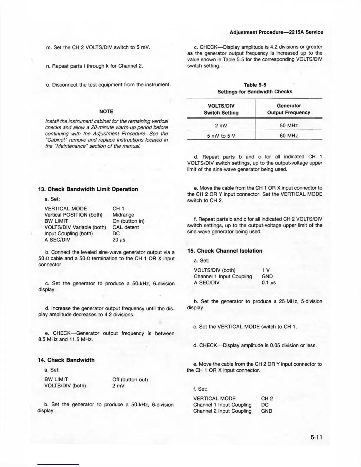
c. CHECK— Display amplitude is 4.2 divisions or greater
as the generator output frequency is increased up to the
value shown in Table 5-5 for the corresponding VOLTS/DIV
switch setting.
Table 5-5
Settings for Bandwidth Checks
VOLTS/DIV
Generator
Switch Setting
Output Frequency
2 mV 50 MHz
5 mV to 5 V
60 MHz
d. Repeat parts b and c for all indicated CH 1
VOLTS/DIV switch settings, up to the output-voltage upper
limit of the sine-wave generator being used.
e. Move the cable from the CH 1 OR X input connector to
the CH 2 OR Y input connector. Set the VERTICAL MODE
switch to CH 2.
f. Repeat parts b and c for all indicated CH 2 VOLTS/DIV
switch settings, up to the output-voltage upper limit of the
sine-wave generator being used.
15. Check Channel Isolation
a. Set:
VOLTS/DIV (both) 1 V
Channel 1 Input Coupling GND
A SEC/DIV 0.1
ns
b. Set the generator to produce a 25-MHz, 5-division
display.
c. Set the VERTICAL MODE switch to CH 1.
d. CHECK— Display amplitude is 0.05 division or less.
e. Move the cable from the CH 2 OR Y input connector to
the CH 1 OR X input connector.
f. Set:
VERTICAL MODE CH 2
Channel 1 Input Coupling DC
Channel 2 Input Coupling GND
5-11