1-18
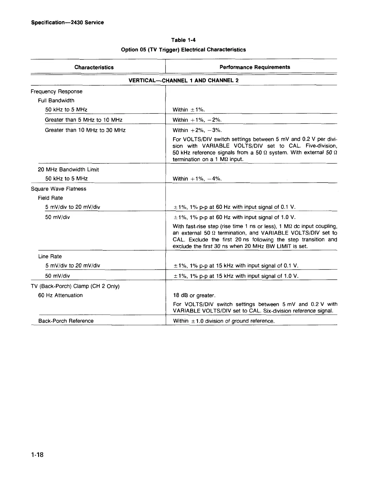
Frequency Response
Full Bandwidth
50 kHz to 5 MHz
Within ± 1%.
Greater than 5 MHz to 10 MHz
Within + 1%, - 2%.
Greater than 10 MHz to 30 MHz Within +2%, -3%.
For VOLTS/DIV switch settings between 5 mV and 0.2 V per divi-
sion with VARIABLE VOLTS/DIV set to CAL.
Five-division,
50 kHz reference signals from a 50 Q system. With external 50 Q
termination on a 1 MQ input.
20 MHz Bandwidth Limit
50 kHz to 5 MHz Within +1%, -4%.
Square Wave Flatness
Field Rate
5 mV/div to 20 mV/div ± 1%, 1% p-p at 60 Hz with input signal of 0.1 V.
50 mV/div ± 1%, 1% p-p at 60 Hz with input signal of 1.0 V.
With fast-rise step (rise time 1 ns or less), 1 MQ dc input coupling,
an external 50 Q termination, and VARIABLE VOLTS/DIV set to
CAL. Exclude the first 20 ns following the step transition and
exclude the first 30 ns when 20 MHz BW LIMIT is set.
Line Rate
5 mV/div to 20 mV/div ± 1%, 1% p-p at 15 kHz with input signal of 0.1 V.
50 mV/div ± 1%, 1% p-p at 15 kHz with input signal of 1.0 V.
TV (Back-Porch) Clamp (CH 2 Only)
60 Hz Attenuation 18 dB or greater.
For VOLTS/DIV switch settings between 5 mV and 0.2 V with
VARIABLE VOLTS/DIV set to CAL. Six-division reference signal.
Back-Porch Reference Within ± 1.0 division of ground reference.
VERTICAL-CHANNEL 1 AND CHANNEL 2
Performance Requirements
Characteristics
Table 1-4
Option 05 (TV Trigger) Electrical Characteristics
Specification-2430 Service