TM 11-6625-2735-14-1
R1664, distribute the drive evenly between the four
transistors, C1652, C1662, C1654 and C1664 degenerate
the high frequency response and reduce transients.
Feedback to maintain inverter operation is provided
from T1400 primary to T1631 primary through R1626,
R1631, R1633, CR1632 and CR1634. Resistors R1626 and
R1631 provide frequency stability and current limiting.
R1633, CR1632, and CR1634 compensate for differences
in transistors and components. CR1632 and CR1634
conduct during different inverter half-cycles and permit
R1633 to balance the drive to T1400.
C1681, C1682, C1683, C1684, C1685 and C1686 are
added to the secondary of T1400 with Option 7 to provide
optimum reduction of transients during inverter opera-
tion.
DC Input
External power is applied through P1601. CR1601 is
normally reverse biased. If the wrong polarity external
power is applied, CR1601 becomes forward biased and
blows fuse F1601. Low-pass network T1601, C1601,
C1603, and C1609 is a filter to reduce transients to the dc
source.
Start-Stop Switch
S1601, Section A in the off (stop) position discharges
the capacitors in the turn-off and start circuits. This
ensures the correct time constants when S1601 is chang-
ed to the on (start) position. In the start position, the dc
input is applied to the inverter circutiry by S1601, Section
A. At the same time S1601, section B is closed, completing
the feedback loop for the inverter transistors, S1601,
section B stops the inverter in the off position by opening
the feedback loop between T1400 and T1631.
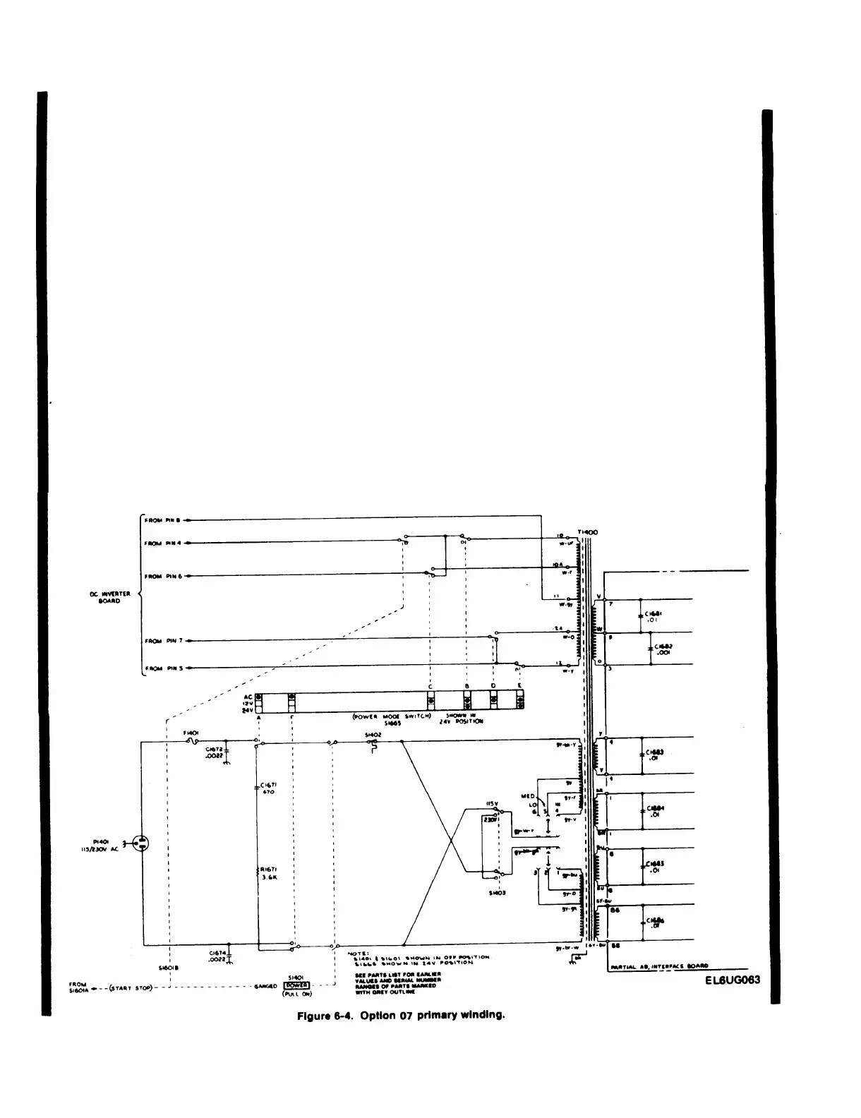
Power-Mode Switch (S1665)
See Figure 6-4. Sections A and F connect filter C1671
and R1671 to T1400 during 12 or 24 V operation to reduce
converter transients. Sections C and D select either trans-
former terminals 10A and 12A or 10 and 12, to provide the
same secondary output when operating on 12 or 24 V.
Sections Band E connect transformer terminals 10 and 12
to S1665, C and D, and to the inverter feedback circuit
during both 12 and 24 V operation.
6-2.4 Change 1
 Loading...


