Circuit Board Chassis Removal
The circuit board is mounted on a small chassis located
between the power transformer and the crt shield. To
remove the chassis, remove three screws. Two thread-
forming screws are located at the top of the chassis. One
screw is at the bottom of the chassis and is removed from
the right-hand side by going just below the power
transformer.
TM 11-6625-2735-14-1
3. 1106 Power Supply battery pack.
2
4. Two 12-volt wet-cell storage batteries, in series,
tapped at 20, 22, or 24 V.
3
5. 18 to 23 Ni Cd cells, 4.0 amp hr (D cells) or greater,
furnishing 20 to 28 V.
3
CHECKOUT
Option 7 may be checked without removing it from the
oscilloscope. Test voltages are shown in figure 6-6; ideal-
ized waveforms in figure 6-7. The reference letters (A), (B),
etc., refer to points indicated on the schematic and circuit
board illustrations.
Equipment Required
DC VOLTMETER. 22 V to 28 V.
TEST OSCILLSOCOPE. Used to verify the inverter
balance adjustment. If the instrument under test and
Option 7 are operational and the power source has a
negative ground, they may be used as the test os-
cilloscope for this check.
DC POWER SOURCE. Voltage from 22 V to 28 V and
from 11.5 V to 14 V. A source voltage of less than 22 volts
will turn off Option 7 when it is operating in the 24 V mode.
Starting current in 24 V mode is approximately 4 to 10 A.
The dc source must be capable of handling this surge
without dropping to 22 V or less. The 12 V starting surge is
approximately 15 A.
NOTE
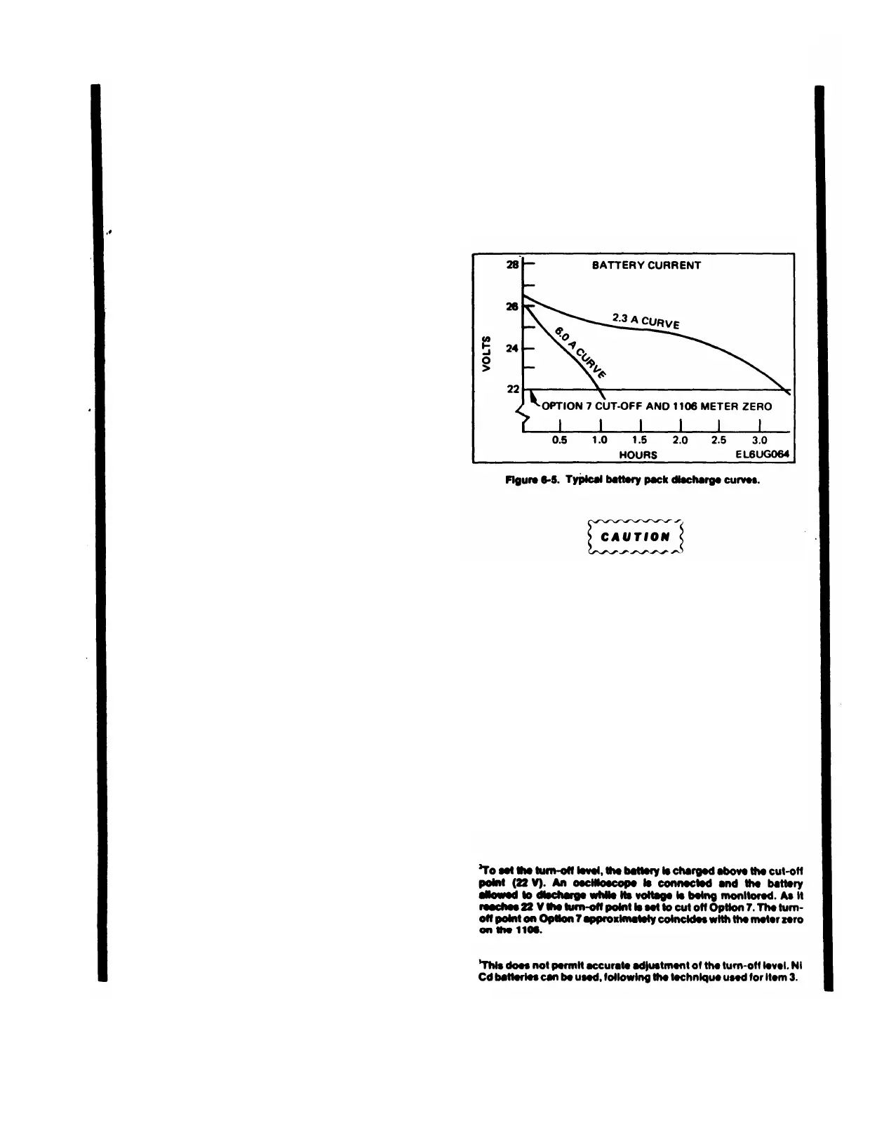
Option 7 is calibrated at the factory using a power
supply (having the specifications listed first under
the equipment required list). This permits the most
accurate setting of the turn-off volts and inverter
balance adjustments. Because this type of power
supply may not be available, several alternate
possibilities are given. The alternate power supplies
have drawbacks, including voltage stability vs. time
with high discharge rates, see figure 6-5.
1. Variable power supply with the aforementioned
capabilities.
2. Variable power supply with an adequate current
rating, in series with items 4 or 5.
This procedure is for an external dc source with the
negative lead at ground potential (negative ground
system).
Operating Range
a. Connect the dc source to the oscilloscope equipped
with Option 7. Operate the oscilloscope in the 24 V mode.
Connect the voltmeter between fuse, F1601 (B) and the
common negative return (A). Vary the dc source from 28 V
to 22 V.
CHECK—Oscilloscope should operate over the
voltage range.
Change 1 6-2.5
 Loading...


