Theory of operation
24
AFG31000 Series Arbitrary Function Generator Service Manual
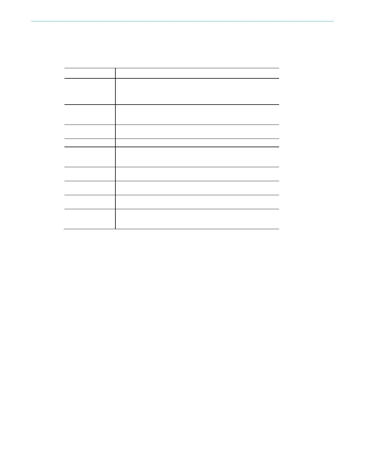
Platform section
Instrument area Description
Contains the power switch, one ac line voltage (100~240 V ac) out
to Artesyn power supply and another ac line voltage (100~240 V
ac) pass rectifier and filter circuit out (120 V~370 V dc) to TDK-
CPU circuit
Contains an MPU, EMMC, and SDRAM to control the instrument.
The liquid crystal display controller and the USB circuit are
Stabilizes and supplies +3.3 V and +5.0 V for the logic circuit. 4.2 V
for CPU Power Management Integrated Circuit.
The CPU board contains a GPIB and LAN driver circuit.
communication
Use a FPGA for CPU board and SG board communication.
The Reference Clock Input/output, the Modulation Input and Add in
signals are transmitted from SG board to this board.
Contains an MPU to address keypad input and transition to CPU
board response.
The display is a TFT LCD, 9.0 Inches with 800 x 480 resolution,
controlled by CPU board LCD with RGB mode.
A 92 mm by 92 mm size, dc 12 V type fan. It is driven by fan
controller on the SG board and be transmitted to CPU board output

 Loading...


