Removal and installation
46
AFG31000 Series Arbitrary Function Generator Service Manual
Module rear chassis upper removal and installation
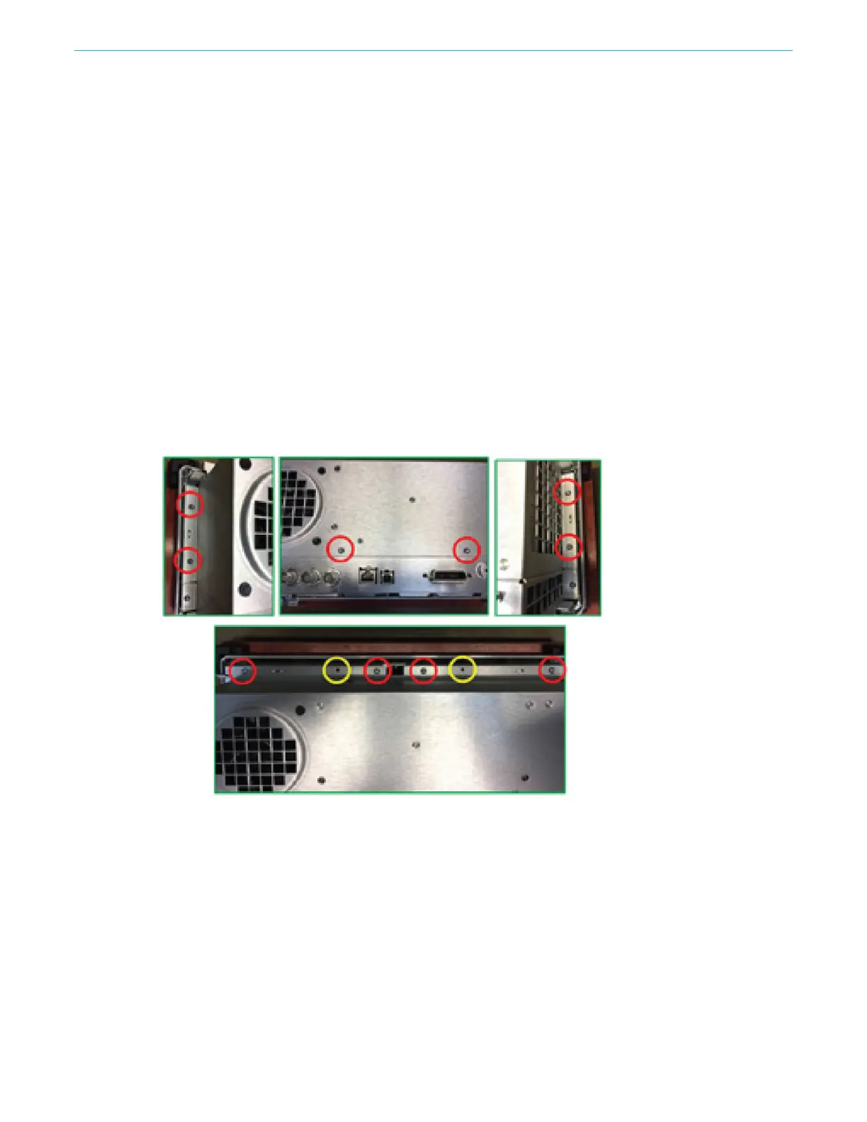
You will need a torque-limiting Torx T-15 screwdriver for this procedure. Refer to the following figure
and follow the steps below to remove the module rear chassis upper.
To remove the module rear chassis upper:
1. Remove the ten screws attaching the module rear chassis upper to the front chassis and the
module rear chassis-bottom. Eight screws are on the front chassis. Two screws are on the
module rear chassis-bottom.
2. Disconnect the following cables:
a. Two (2) pin fan cable from fan
b. Four (4) pin power cable (from main power supply to CPU board)
c. Seven (7) pin power cable (from main power supply to signal generator board)
d. Four (4) pin power cable (from auxiliary power supply to signal generator board)
e. Three (3) pin power cable (from main power supply to CPU board)
f. Three (3) pin cable (from auxiliary power supply to CPU board)
3. Lift the module rear chassis upper off.
To install the module rear chassis upper, perform the removal procedure in reverse order.
Figure 18: Module rear upper chassis upper
 Loading...


