Removal and installation
AFG31000 Series Arbitrary Function Generator Service Manual
53
CPU board and power receptacle removal and installation
You will need torque-limiting Torx T-15, T-10, and T-8 screwdrivers for this procedure. Refer to the
following figure and steps below to remove the front panel board and keypad.
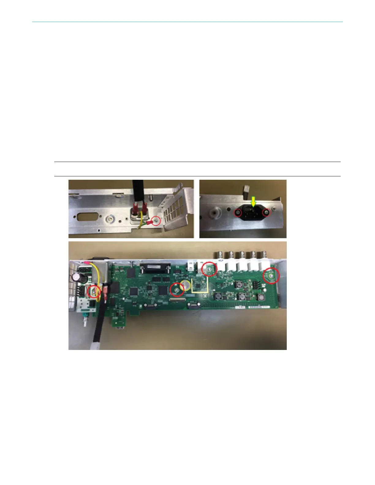
To remove the CPU board and power receptacle:
1. Disconnect the cables.
2. Remove one screw attaching the grounding cable to the chassis by using the T-10 screwdriver.
Remove the two screws attaching the power receptacle to the chassis using the T-8 screwdriver.
3. Remove the power receptacle.
4. Remove the four screws attaching the CPU board to the rear bottom-chassis using the T-15
screwdriver.
5. Remove the five BNC nuts and washers using the 16 mm socket driver.
6. Remove the two black GPIB hex screws using the 7 mm socket driver.
7. Pull out the CPU board.
NOTE: To reconnect all the parts, perform the removal procedure in reverse order.
Figure 29: Power receptacle
 Loading...