Removal and installation
54
AFG31000 Series Arbitrary Function Generator Service Manual
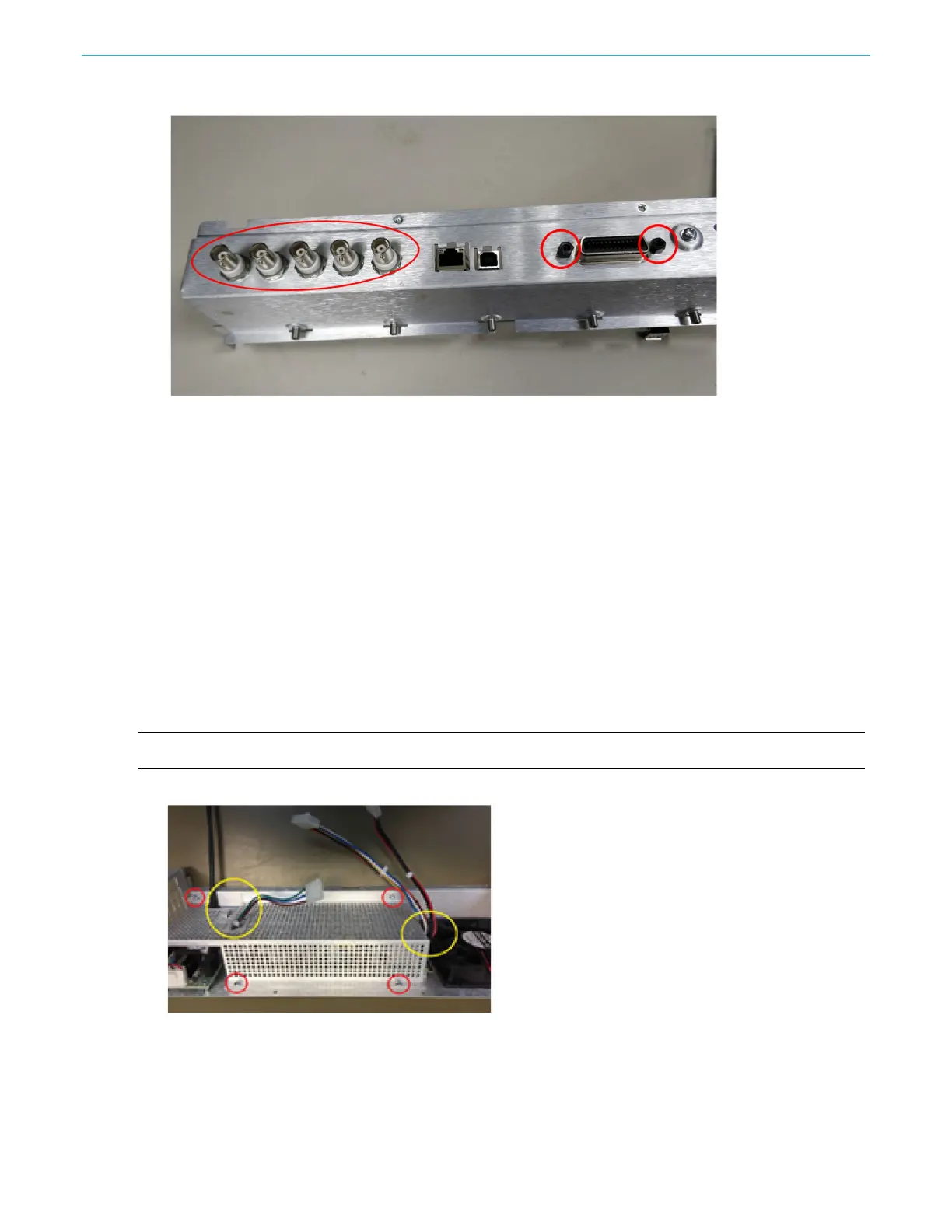
Figure 30: Remove the BNC nuts and GPIB hex screws.
Power supply and fan removal and installation
You will need needle-nose pliers and a torque-limiting Torx T-15 screwdriver for this procedure. Refer
to the following figure and follow the steps below to remove or install all the parts.
To remove the power supply and fan:
1. Remove the four screws attaching the safety cover to the chassis by using a T-15 screwdriver.
2. Remove the safety cover.
3. Remove the four screws attaching the auxiliary power supply to the chassis using a T-15
screwdriver. Remove the four screws attaching the main power supply to the chassis using a
T-15 screwdriver. The auxiliary power supply is only applicable for the two-channel unit.
4. Remove the main power supply (and auxiliary power supply, if applicable).
5. Remove the four grommets attaching the fan to the chassis using needle-nose pliers.
6. Remove fan.
NOTE: To reconnect all the parts, perform the removal procedure in reverse order.
Figure 31: Safety cover

 Loading...


