Connecting the interlock
The following figure shows the location of the interlock connector on the rear panel of the
4200A-SCS.
To connect the interlock:
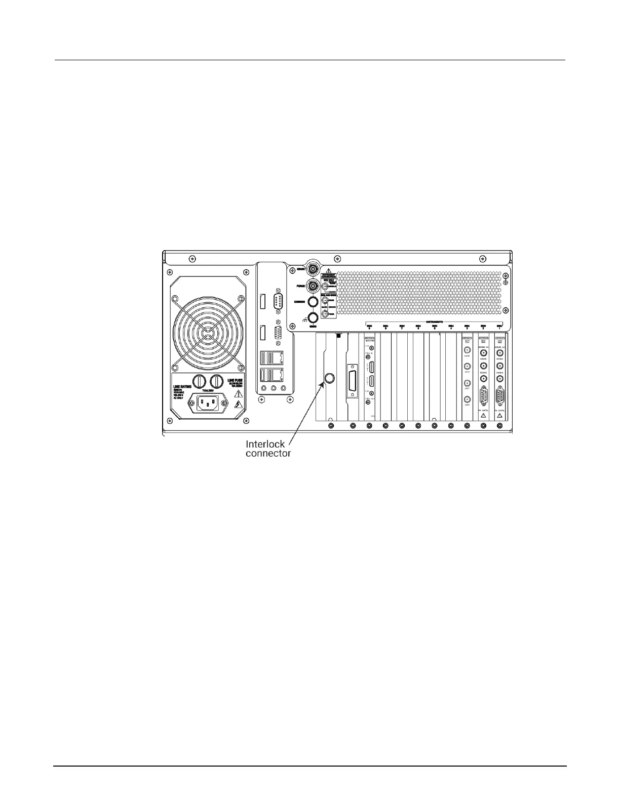
1. Connect one end of the supplied 236-ILC-3 interlock cable to the interlock connector on the rear
panel of the 4200A-SCS (see the following figure).
Figure 8: Interlock connector on the rear panel of the 4200A-SCS
2. Connect the other end of the interlock cable to a compatible test fixture.
Configuring safety interlock operation
The following figure shows typical interlock connector wiring. A normally open switch should be used
so that an open interlock condition occurs when the switch is open.
Many test fixtures have a safety interlock connected to the instrument lid. When the lid is closed, the
interlock circuit is closed (asserted), and SMU ±200 V ranges are enabled. Conversely, the interlock
circuit is open (deasserted) when the lid is open, and SMU ±200 V ranges are disabled.

 Loading...


