Adjustments
DC CMRR
WARNING. Dang
erous voltages will be present on the calibration generator output terminals and connection cables. Always
verify that the generator is in the standby mode before y ou make any connections to the generator.
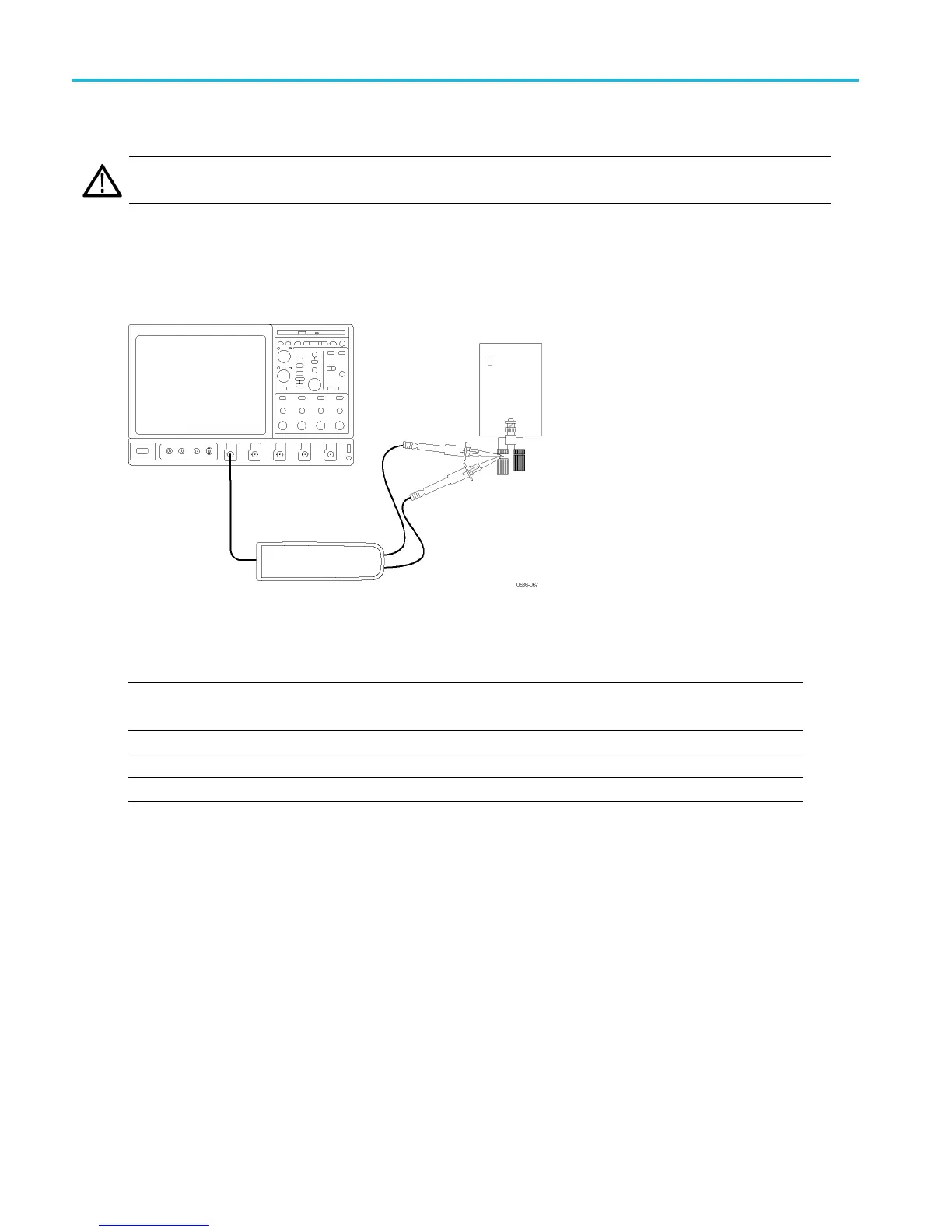
1. Verify that the generator output is off.
2. Connect both of the probe inputs to the red (+) banana connector on the front output terminals of the generator. Use a
BNC-banana adapter i
f necessary.
3. Set the output of the generator to the voltage and frequency listed in the table. (See Table 17.)
Table 17: DC CMRR test equipment settings
Probe Generator output
Model Range Voltage (rms) Voltage (p-p) Frequency
THDP0100 600 V 353.53 V 1000 V 40 Hz
THDP0200 150 V 200 V 566 V 40 Hz
TMDP0200 75 V 353.53 V 1000 V 40 Hz
4. Set the osci
lloscope horizontal to 10 ms/div and bandwidth to 5 MHz.
5. Set the p rob
e attenuation to the lower (most sensitive) range of the probe.
6. Enable the g
enerator output. Set the oscilloscope vertical to display the signal. For a stable display, connect the
generator Sense output to another channel and trigger off of that channel.
47 THDP0100/0200 & TMDP0200 High Voltage Differential Probes Instruction Manual
 Loading...


