Adjustments
LF Compensation
WARNING. Dang
erous voltages will be present on the calibration generator output terminals and connection cables. Always
verify that the generator is in the standby mode before y ou make any connections to the generator.
NOTE. The TMDP0200 probe only has one long-term +LF adjustment and one long-term –LF adjustment. The other two
probe models have two
long-term +LF adjustments and two long-term –LF adjustments each.
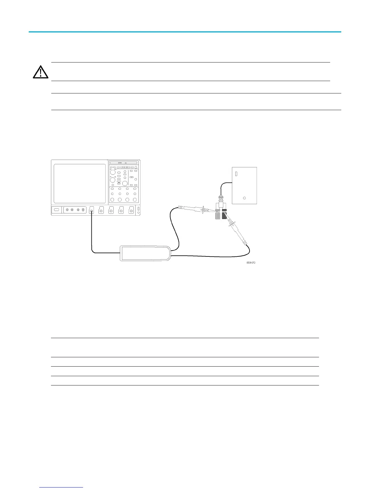
1. Verify that the generator output is off.
2. Connect the probe inputs to the signal output connector on the back of the generator, using adapters if necessary.
Connect the red probe lead to the signal, and the black lead to ground.
3. Set the probe attenuation to the lower range for the probe that you are adjusting.
4. Set the oscilloscope horizontal to 4 μs/div, acq mode = average 16.
5. Set the generator fast-rise (rise time waveform) output frequency to 10 kHz.
6. Set the generator fast-rise output voltage to 50 V
p-p
.
Table 18: LF c
ompensation test equipment settings
Probe Generator output
Model Range Voltage (p-p) Frequency
THDP0100 600 V 50 V 10 kHz
THDP0200 150 V 50 V 10 kHz
TMDP0200 75 V 50 V 10 kHz
7. Enable the generator output. Set the oscilloscope vertical to display the signal.
49 THDP0100/0200 & TMDP0200 High Voltage Differential Probes Instruction Manual
 Loading...


