Section 9 - Diagnostics
9-4
VM700A Option 01 (NTSC) & Option 11 (PAL) User Manual
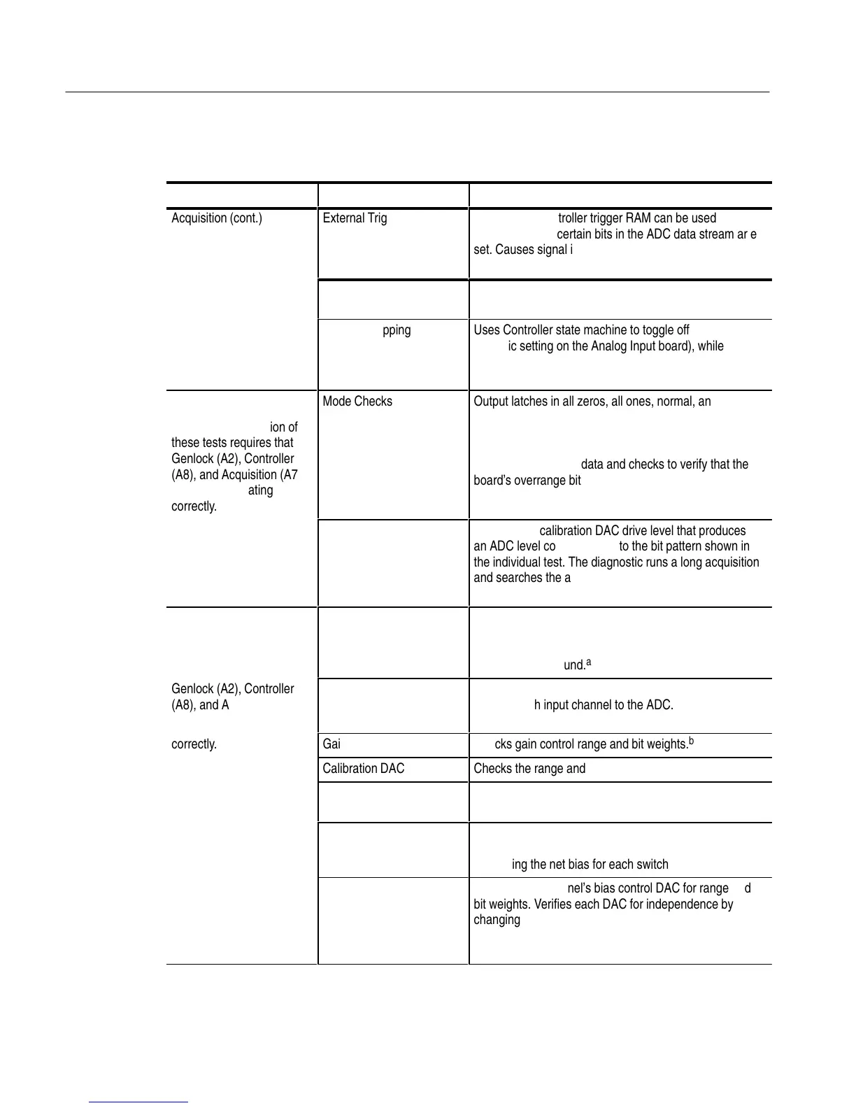
Table 9-2: Individual Diagnostics (Cont.)
Board Tested DescriptionTest Name
ÁÁÁÁÁÁ
ÁÁÁÁÁÁ
Acquisition (cont.)
ÁÁÁÁÁÁ
ÁÁÁÁÁÁ
External Triggers
ÁÁÁÁÁÁÁÁÁÁÁÁÁ
ÁÁÁÁÁÁÁÁÁÁÁÁÁ
Checks that Controller trigger RAM can be used to
recognize when certain bits in the ADC data stream ar e
set. Causes signal interrupts that are counted by the
Controller’s Sig0, Sig1, Sig2 counters.
ÁÁÁÁÁÁ
ÁÁÁÁÁÁ
Long Acquisitions
ÁÁÁÁÁÁÁÁÁÁÁÁÁ
Runs long acquisitions to verify interaction of the
Controller and the Acquisition state machines.
ÁÁÁÁÁÁ
ÁÁÁÁÁÁ
ÁÁÁÁÁÁ
ÁÁÁÁÁÁ
ÁÁÁÁÁÁ
ÁÁÁÁÁÁ
Sample Dropping
ÁÁÁÁÁÁÁÁÁÁÁÁÁ
ÁÁÁÁÁÁÁÁÁÁÁÁÁ
ÁÁÁÁÁÁÁÁÁÁÁÁÁ
Uses Controller state machine to toggle offset level (a
dynamic setting on the Analog Input board), while a long
acquisition runs. Analyzes the acquired data to detect
missing samples.
ÁÁÁÁÁÁ
ÁÁÁÁÁÁ
ÁÁÁÁÁÁ
ÁÁÁÁÁÁ
ÁÁÁÁÁÁ
ADC
Successful completion of
these tests requires that
Genlock (A2), Controller
(A8), and Acquisition (A7)
boards be operating
correctly.
ÁÁÁÁÁÁ
ÁÁÁÁÁÁ
ÁÁÁÁÁÁ
ÁÁÁÁÁÁ
ÁÁÁÁÁÁ
Mode Checks
ÁÁÁÁÁÁÁÁÁÁÁÁÁ
ÁÁÁÁÁÁÁÁÁÁÁÁÁ
ÁÁÁÁÁÁÁÁÁÁÁÁÁ
ÁÁÁÁÁÁÁÁÁÁÁÁÁ
ÁÁÁÁÁÁÁÁÁÁÁÁÁ
Output latches in all zeros, all ones, normal, and
overflow-bit modes and checks the ADC output by
running an acquisition and scanning acquired data. The
overflow bit test generates a drive level to overrange the
board, then acquires data and checks to verify that the
board’s overrange bit was set.
ÁÁÁÁÁÁ
ÁÁÁÁÁÁ
ÁÁÁÁÁÁ
Tests involving the Calibra-
tion DAC require that the
Analog Input (A1) board be
operating correctly.
ÁÁÁÁÁÁ
ÁÁÁÁÁÁ
ÁÁÁÁÁÁ
Bit Patterns
ÁÁÁÁÁÁÁÁÁÁÁÁÁ
ÁÁÁÁÁÁÁÁÁÁÁÁÁ
ÁÁÁÁÁÁÁÁÁÁÁÁÁ
Generates a calibration DAC drive level that produces
an ADC level corresponding to the bit pattern shown in
the individual test. The diagnostic runs a long acquisition
and searches the acquired data for the individual test’s
bit pattern.
ÁÁÁÁÁÁ
ÁÁÁÁÁÁ
Analog Input
Successful completion of
these tests requires that
ÁÁÁÁÁÁ
ÁÁÁÁÁÁ
DVM
ÁÁÁÁÁÁÁÁÁÁÁÁÁ
ÁÁÁÁÁÁÁÁÁÁÁÁÁ
Calibrates the DVM to the standard gating patterns for
both TV standards (and the gating pattern that enables
the DVM for all video lines) using a precise 1.000 volt
reference and ground.
a
ÁÁÁÁÁÁ
ÁÁÁÁÁÁ
Genlock (A2), Controller
(A8), and Acquisition (A7)
boards be operating
ÁÁÁÁÁÁ
ÁÁÁÁÁÁ
DC Paths
ÁÁÁÁÁÁÁÁÁÁÁÁÁ
ÁÁÁÁÁÁÁÁÁÁÁÁÁ
Checks that a nominal DC voltage can be routed
through each input channel to the ADC.
correctly.
Gain Control
ÁÁÁÁÁÁÁÁÁÁÁÁÁÁÁ
ÁÁÁÁÁÁÁÁÁÁÁÁÁÁÁ
Checks gain control range and bit weights.
b
Calibration DAC
ÁÁÁÁÁÁÁÁÁÁÁÁÁÁÁ
ÁÁÁÁÁÁÁÁÁÁÁÁÁÁÁ
Checks the range and bit weights of the calibration DAC.
ÁÁÁÁÁÁ
ÁÁÁÁÁÁ
Offset Control
ÁÁÁÁÁÁÁÁÁÁÁÁÁ
Checks the range and bit weights of the offset-control
DAC.
ÁÁÁÁÁÁ
ÁÁÁÁÁÁ
Input Selection
ÁÁÁÁÁÁÁÁÁÁÁÁÁ
Checks the input selection switch by setting the channel
bias DACs to different levels on each channel and
measuring the net bias for each switch setting.
ÁÁÁÁÁÁ
ÁÁÁÁÁÁ
ÁÁÁÁÁÁ
ÁÁÁÁÁÁ
ÁÁÁÁÁÁ
ÁÁÁÁÁÁ
Bias Control Range (for
each channel)
ÁÁÁÁÁÁÁÁÁÁÁÁÁ
ÁÁÁÁÁÁÁÁÁÁÁÁÁ
ÁÁÁÁÁÁÁÁÁÁÁÁÁ
Checks each channel’s bias control DAC for range and
bit weights. Verifies each DAC for independence by
changing the other two and monitoring the one being
tested to verify that its range and bit weight remain
unchanged.