Section 2 - Installation and Operation
2-8
VM700A Option 01 (NTSC) & Option 11 (PAL) User Manual
capacity, RTS goes inactive, indicating to the sending device to stop
transmitting data.
With Flow Control (None or XON/XOFF selected), RTS is always
active.
Pin 5 - CTS (Clear To Send).
With Flow Control (CTS/RTS selected), the VM700A is enabled to
transmit data by a high level on pin 5, and is disabled by a low level. It
is normally connected to the RTS line of a terminal.
With Flow Control (None or XON/XOFF selected), the VM700A
transmits data regardless of the CTS level.
Pin 7 - Signal Ground.
Pin 8 - CD (Carrier Detect). This signal typically comes from a modem and
indicates that a phone connection is made.
Pin 20 - DTR (Data Terminal Ready). This pin is always high when the
VM700A is turned on. Modems typically require this signal to be a high
level or they won’t answer the phone.
Table 2-1 gives cable configurations that should work in most instances. The pin
numbers given for the Terminal (DTE) are the most common locations for the
corresponding signals. Note that there is considerable deviation from this
“common” configuration and that not all devices use control lines in the manner
described under this topic. Refer to the instruction manual of the equipment you
are connecting to the VM700A to determine exactly how it should be connected.
Note also that both ends of the DTE to DTE cable are typically female DB-25
connectors. The DTE to DCE cable is female on the VM700A (DTE) end, and
typically male on the modem (DCE) end. See the VM700A Programmer’s
Reference Manual for more information on connecting the VM700A for remote
operation and cable wiring diagrams.
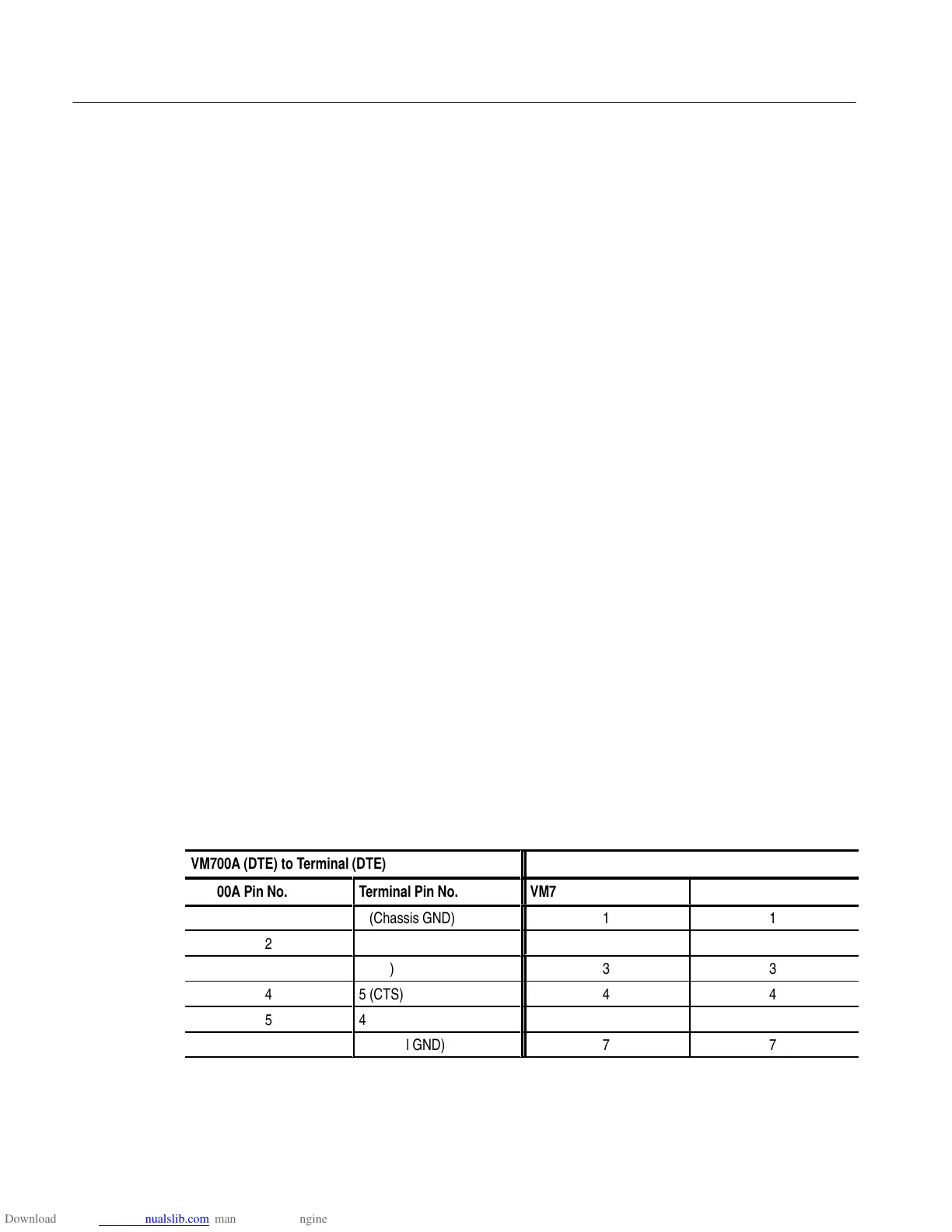
Table 2-1: Typical RS-232C Cable Wiring
ÁÁÁÁÁÁÁÁÁÁÁÁÁÁÁ
ÁÁÁÁÁÁÁÁÁÁÁÁÁÁÁ
VM700A (DTE) to Terminal (DTE)
ÁÁÁÁÁÁÁÁÁÁÁÁÁÁÁ
ÁÁÁÁÁÁÁÁÁÁÁÁÁÁÁ
VM700A (DTE) to Modem (DCE)
VM700A Pin No.
Terminal Pin No.
VM700A Pin No.
Modem Pin No.
1
1 (Chassis GND)
1
1
2
3 (RX)
2
2
ÁÁÁÁÁÁ
3
ÁÁÁÁÁÁ
2 (TX)
ÁÁÁÁÁÁ
3
ÁÁÁÁÁÁ
3
4
5 (CTS)
4
4
5
4 (RTS)
5
5
7
7 (Signal GND)
7
7