Section 9 - Diagnostics
VM700A Option 01 (NTSC) & Option 11 (PAL) User Manual
9-3
Individual Diagnostics
Table 9-2 lists and describes the VM700A individual diagnostics.
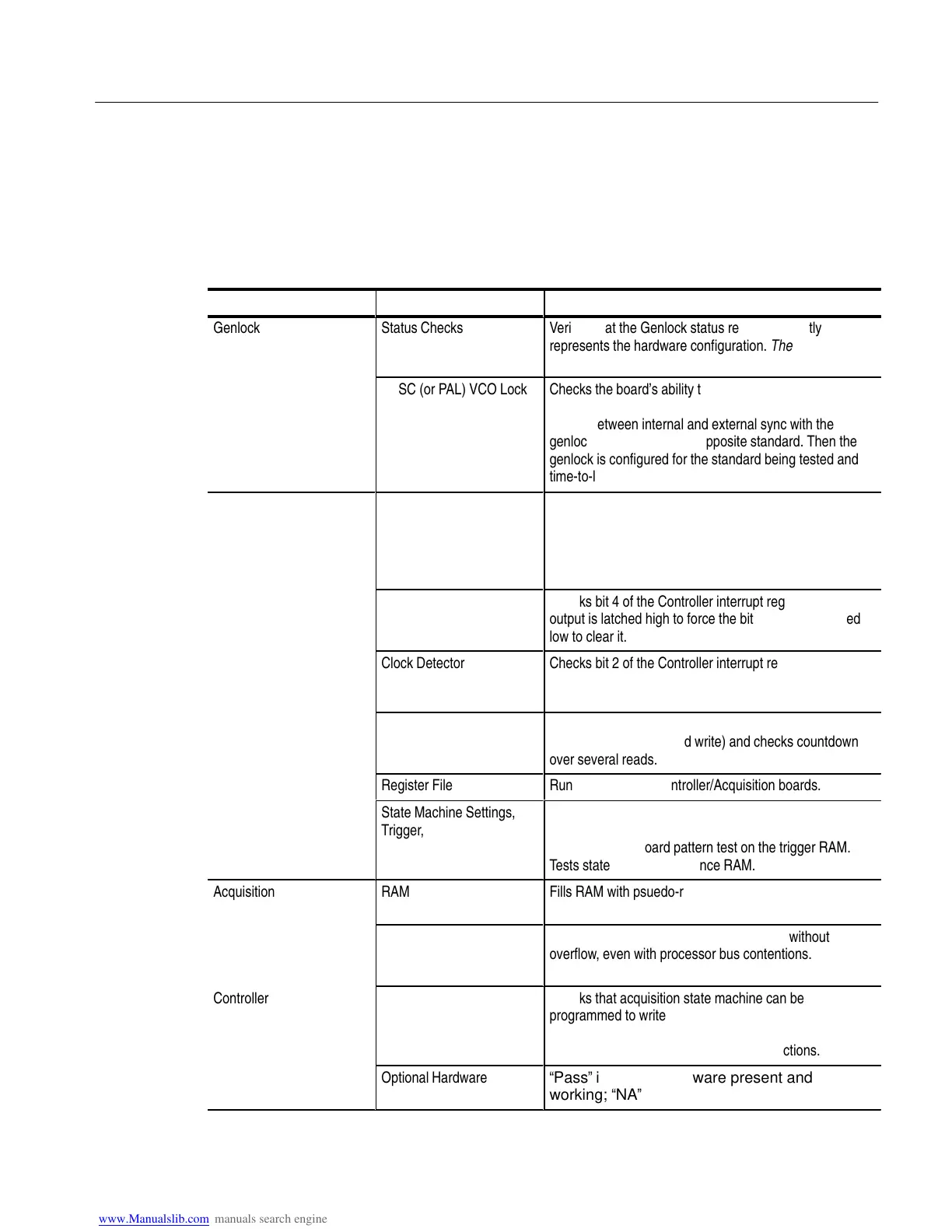
Table 9-2: Individual Diagnostics
Board Tested Test Name Description
ÁÁÁÁÁÁ
Genlock
ÁÁÁÁÁÁ
Status Checks
ÁÁÁÁÁÁÁÁÁÁÁÁÁ
Verifies that the Genlock status register correctly
represents the hardware configuration. These tests must
pass to run the lock tests.
ÁÁÁÁÁÁ
ÁÁÁÁÁÁ
ÁÁÁÁÁÁ
ÁÁÁÁÁÁ
Successful completion of
these tests requires that
the Controller (A8) be
operating correctly.
ÁÁÁÁÁÁ
ÁÁÁÁÁÁ
ÁÁÁÁÁÁ
ÁÁÁÁÁÁ
NTSC (or PAL) VCO Lock
ÁÁÁÁÁÁÁÁÁÁÁÁÁ
ÁÁÁÁÁÁÁÁÁÁÁÁÁ
ÁÁÁÁÁÁÁÁÁÁÁÁÁ
ÁÁÁÁÁÁÁÁÁÁÁÁÁ
Checks the board’s ability to acquire and hold lock using
each VCO. The test forcefully breaks lock by toggling
rapidly between internal and external sync with the
genlock configured for the opposite standard. Then the
genlock is configured for the standard being tested and
time-to-lock is measured.
ÁÁÁÁÁÁ
ÁÁÁÁÁÁ
ÁÁÁÁÁÁ
Controller
ÁÁÁÁÁÁ
ÁÁÁÁÁÁ
ÁÁÁÁÁÁ
Control Registers
ÁÁÁÁÁÁÁÁÁÁÁÁÁ
ÁÁÁÁÁÁÁÁÁÁÁÁÁ
ÁÁÁÁÁÁÁÁÁÁÁÁÁ
Checks mode, Genlock configuration, Genlock status,
and filter control registers with 8-bit walking-1 and
walking-0 patterns. Checks analog input register for
writeability (no bus errors). Checks DVM readback
register for readability.
ÁÁÁÁÁÁ
ÁÁÁÁÁÁ
ÁÁÁÁÁÁ
ÁÁÁÁÁÁ
Overrange Detector
ÁÁÁÁÁÁÁÁÁÁÁÁÁ
ÁÁÁÁÁÁÁÁÁÁÁÁÁ
Checks bit 4 of the Controller interrupt register. ADC
output is latched high to force the bit to set, and latched
low to clear it.
ÁÁÁÁÁÁ
ÁÁÁÁÁÁ
Clock Detector
ÁÁÁÁÁÁÁÁÁÁÁÁÁ
Checks bit 2 of the Controller interrupt register. Disables
the sample clock to cause the bit to set, then re-enables
the sample clock to clear the bit.
ÁÁÁÁÁÁ
ÁÁÁÁÁÁ
ÁÁÁÁÁÁ
ÁÁÁÁÁÁ
Clamp Counters (A—C)
and Acq Sig Counters
(Sig0—Sig2)
ÁÁÁÁÁÁÁÁÁÁÁÁÁ
ÁÁÁÁÁÁÁÁÁÁÁÁÁ
Checks the counter chips. Performs walking-1 and
walking-0 tests (read and write) and checks countdown
over several reads.
Register File
ÁÁÁÁÁÁÁÁÁÁÁÁÁÁÁ
ÁÁÁÁÁÁÁÁÁÁÁÁÁÁÁ
Runs only on later Controller/Acquisition boards.
ÁÁÁÁÁÁ
ÁÁÁÁÁÁ
ÁÁÁÁÁÁ
ÁÁÁÁÁÁ
State Machine Settings,
Trigger, and Sequence
RAM
ÁÁÁÁÁÁÁÁÁÁÁÁÁ
ÁÁÁÁÁÁÁÁÁÁÁÁÁ
Checks SRUN and TRUN lines of the settings RAM;
control, data, and address lines of the trigger RAM.
Runs a checkerboard pattern test on the trigger RAM.
Tests state machine sequence RAM.
ÁÁÁÁÁÁ
Acquisition
ÁÁÁÁÁÁ
RAM
ÁÁÁÁÁÁÁÁÁÁÁÁÁ
Fills RAM with psuedo-random sequence, then reads
and verifies it.
ÁÁÁÁÁÁ
ÁÁÁÁÁÁ
Successful completion of
these tests requires that
Genlock (A2) and
ÁÁÁÁÁÁ
ÁÁÁÁÁÁ
FIFO
ÁÁÁÁÁÁÁÁÁÁÁÁÁ
ÁÁÁÁÁÁÁÁÁÁÁÁÁ
Checks that data moves through the FIFO without
overflow, even with processor bus contentions.
ÁÁÁÁÁÁ
ÁÁÁÁÁÁ
Controller (A8) boards be
operating correctly.
ÁÁÁÁÁÁ
ÁÁÁÁÁÁ
Load/Looping
ÁÁÁÁÁÁÁÁÁÁÁÁÁ
ÁÁÁÁÁÁÁÁÁÁÁÁÁ
Checks that acquisition state machine can be
programmed to write the contents of temporary store
into acquisition memory locations, and that it can
process acquisition program GOTO instructions.
ÁÁÁÁÁÁ
ÁÁÁÁÁÁ
Optional Hardware
ÁÁÁÁÁÁÁÁÁÁÁÁÁ
“Pass” indicates hardware present and
working; “NA” indicates hardware not available.