Section 3 - Configuring the VM700A
3-18
VM700A Option 01 (NTSC) & Option 11 (PAL) User Manual
Power Up Diagnostics Selection
Genlock~Diagnostic
Controller~Diagnostic
Acquisition~Diagnostic
ADC~Diagnostic
AnalogInput~Diagnostic
FilterBoard~Diagnostic
GPIB~Diagnostic
AudioProcessor~Diagnostic
AudioAnalog~Diagnostic
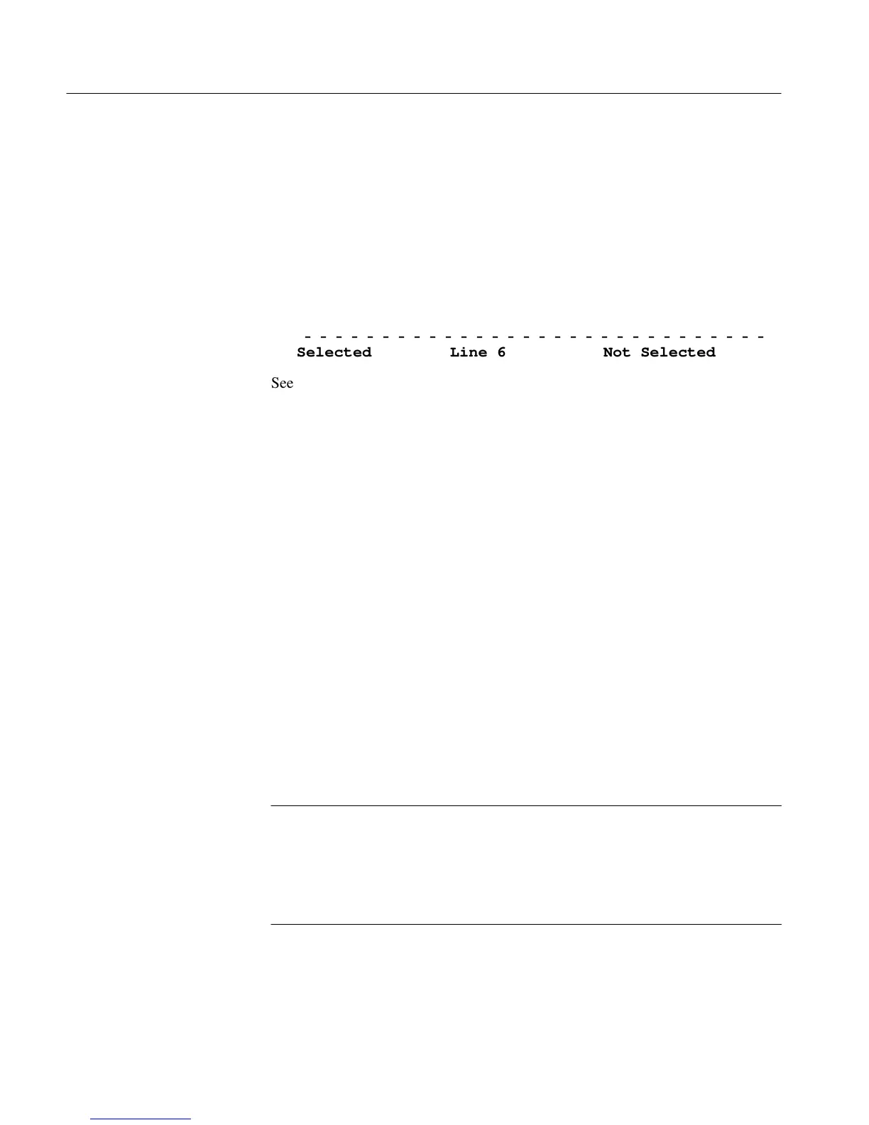
ĆĆĆĆĆĆĆĆĆĆĆĆĆĆĆĆĆĆĆĆĆĆĆĆĆĆĆĆĆĆ
Selected Line 6 Not Selected
See Section 9, Diagnostics, for more information on using and controlling the
diagnostic choices.
The Measure_Limit Files directory contains limit information for Measure mode
(manual) measurements. The limits in these files perform two functions:
1. They place graphic limit markers on the screen in measurements (where
applicable), and
2. They appear on printouts from the Measurement Results directory when the
measurement exceeds the limits.
The measurement limits file used by Measure mode is designated in the active
file in the Video_Source Files directory.
The file(s) in the Measurement Locations directory contain information used by
both Auto and Measure modes. The measurement locations file for each channel
is designated in the active file in the Video_Source Files directory.
For PAL, the SIS Present parameter tells the VM700A whether Sound in Sync is
present (yes) or absent (no). When SIS Present is yes, measurements are made
using Synchronous sampling. The Measure mode parameter determines whether
manual measurements are made with Asynchronous (the default) or Synchronous
sampling.
NOTE. Measure mode (manual) measurements normally use Asynchronous
sampling. Auto measurements always use Synchronous sampling. Synchronous
sampling is available for manual measurements in the case of very noisy signals,
negative-going pulses, or other conditions that prevent using Asynchronous
sampling. However, Synchronous sampling cannot be used to measure VCR/VTR
devices.
The Line parameter contains the default line on which the measurement is made.
The Line value is used in the Default Line Sel. soft key in the Select Line menu
in Measure mode. For PAL, the Time offset from leading edge of sync parameter
defines the actual measurement position. The numeric Line values and Time
Measure_Limit Files
(Directory)
Measurement
Locations (Directory)