Removal and Replacement Procedures
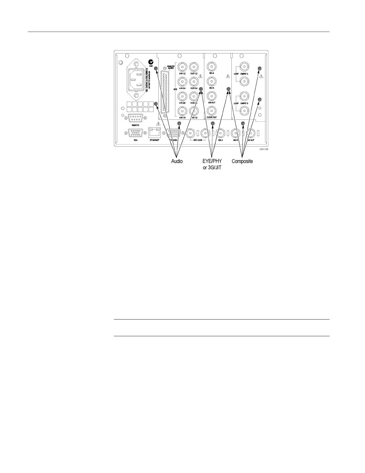
Figure 4-4: Module securing screws
Composite Board (Option
CPS)
The Composite board, if installed, is located in the right module bay. (See
Figure 4-4 on page 4-30.)
1. Remove the four T-15 screws securing t he Composite module to the rear panel.
2. Lift the Composite module out of the instrument, rocking it gently until the
connector separates from J13 on the Main board. It may he lp to loosen the
three screws that hold the EYE/PHY or 3G rear panel (or blank).
Mezza
nine Board
The Mezzanine board, if installed, is located below the right module bay.
1. Remove the nuts securing the three SDI BNC connectors in the lower right
corner of the rear panel.
2. Disconnect the ribbon cable from J4 on the Mezzanine board.
NOTE. Do not pull on the ribbon cable. Grip the body of the connector, or pry the
connector away from the plug with a small screwdriver.
3. Remove the two T-15 screws securing the Mezzanine board to the Main board.
4. Move the Mezzanine board toward the front of the instrument until the BNC
connectors clear the rear panel, then lift it up out of the instrument.
4–30 WFM6120, WFM7020, and WFM7120 Waveform Monitors Service Manual
 Loading...


