Removal and Replacement Procedures
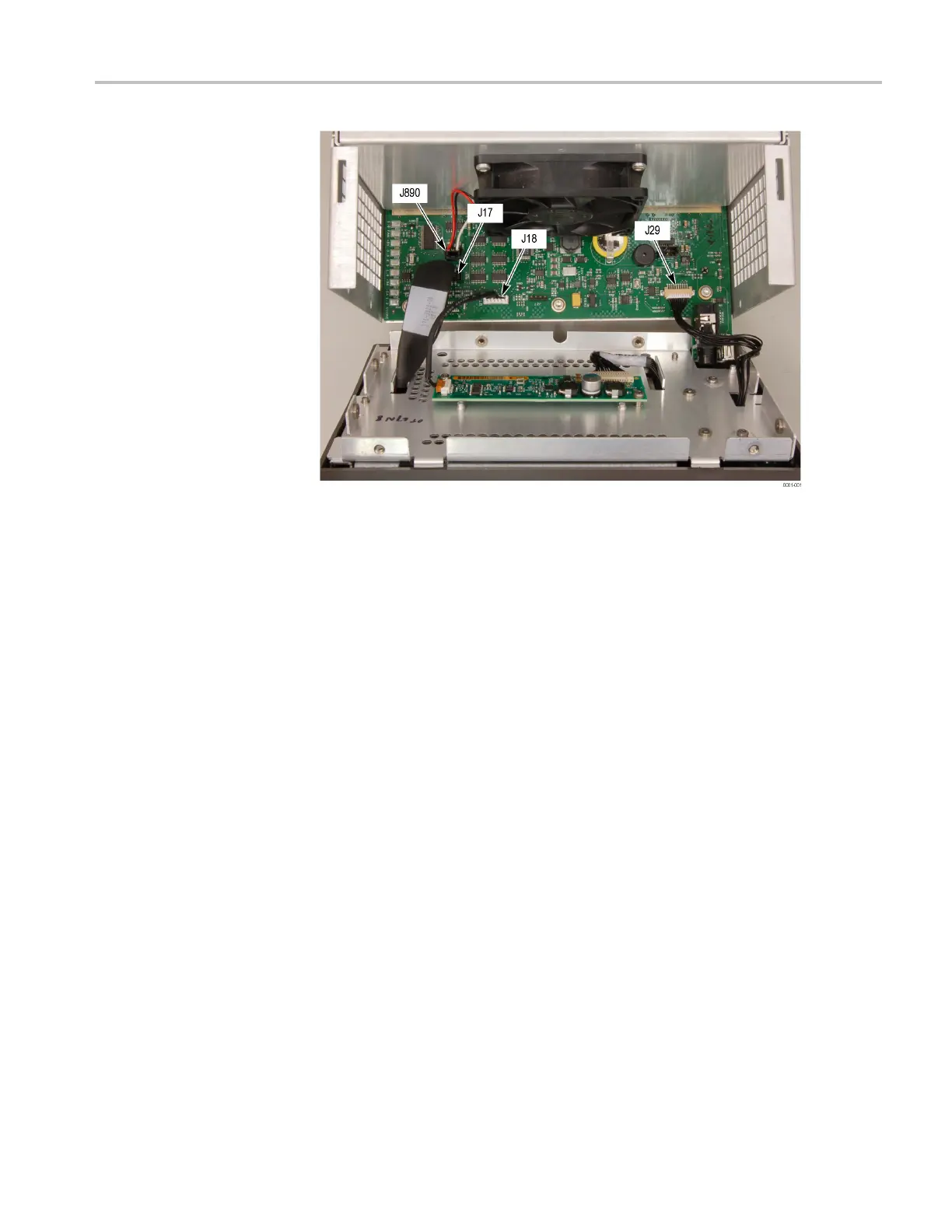
Figure 4-5: Front panel cable connections
Remove t
he bezel from the LCD assembly.
4. Remove the two T10 screws securing the bezel to the Front Panel board.
(See Figure 4-6 on page 4-34.)
5. Remove the two Pozidriv screws securing the bottom of the bezel to the
display bracket.
6. Use a spudger or other tool to pry the bezel clips away from the bracket and
then pull the bezel away, leading the front panel cable through the cutout in
the b
racket.
WFM6120, WFM7020, and WFM7120 Waveform Monitors Service Manual 4–33
 Loading...


