iTRANS 2
FIXED POINT SINGLE OR DUAL GAS MONITOR
WITH DUAL ANALOG OUTPUTS
USER MANUAL
Revision 7.0
IMPORTANT: Use of this product in areas where it may be subject to large amounts of
electromagnetic interference may affect the reliable operation of this device and should be
avoided.
WARNING: Supply wire with a minimum rating of 90°C must be used for interconnection to the
.
NOTE: For classified locations, a “poured” wire seal must be installed within 18 inches (457mm)
of the main unit for both power entry and remote sensors.
NOTE: Remove power from the before making any wiring connections.
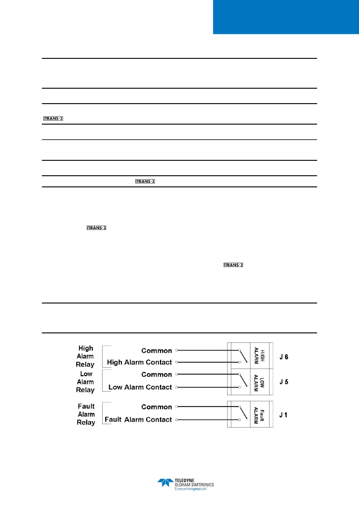
4.3 Alarm Relay Wiring (J1, J5, and J6)
To connect the control wires to the three relay terminals on the relay board, wire the unit
to the connectors shown in Figure 2-4. The low alarm relay is activated when the low alarm
threshold is met. This is a non-latching, Normally Open (NO) contact. The high alarm relay is
activated when the high alarm threshold is met. This is a non-latching, Normally Open (NO)
contact. The fault alarm relay is activated upon power-up of the . When the fault condition
is met, the circuit opens. This is an Electronically closed (NC) contact. See Figure 4-1 for relay
wiring.
NOTE: It is recommended that on-board relays should not be used to drive loads directly. On-
board relays should be used to drive a secondary, higher-power relay which is connected to the
control device (e.g., strobe, siren, exhaust fan, etc.).
Figure 4-1 Alarm Relay Connectors J6, J5 and J1