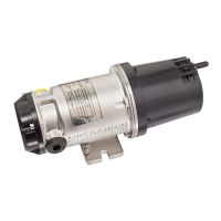
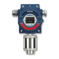
iTRANS 2
FIXED POINT SINGLE OR DUAL GAS MONITOR
WITH DUAL ANALOG OUTPUTS
USER MANUAL
Revision 7.0
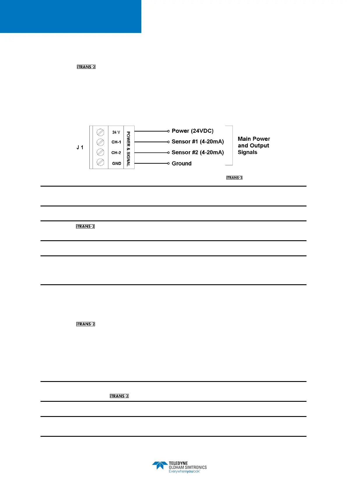
4.4 Power and Output Wiring (J1)
Connect the power and signal wires to the appropriate wiring terminals as follows.
• 24 V:Connect 24 VDC (12-28 VDC) supply power
• CH 1:Channel 1, 4-20 mA output signal
• CH 2:Channel 2, 4-20 mA output signal
• GND:DC return
Figure 4-2 Power and Signal Connector J1 on the
NOTE: Use supplied green conductor for enclosure ground. Public 485 GND is to be used for
ModBus digital ground.
NOTE: The is a 3- or 4-wire 4-20 mA device. For dual sensor configuration you must
have a second 4-20 mA signal wire pulled to the unit.
NOTE: When not using 4-20 mA outputs, use the supplied resistors to connect CH-1 and CH-2
to GND. If these resistors are not connected and the 4-20 mA outputs are not used, a “P” will
appear on the display, indicating an open loop condition.
4.5 Sensor Wiring (J3)
Connect the sensor wires (for on-board, remote or stand-alone) to the appropriate wiring
terminals as follows.
• 24 V:Red wire from sensor head
• 485A:Yellow wire from sensor head
• 485B:Black wire from sensor head
• GND:Green wire from sensor head
NOTE: Shielding from either the controller or remote sensors should be bonded to the enclosure
screw located inside the .
NOTE: The 24 V terminal supplies 24 VDC to the sensor for power. This terminal should not be
connected to the output of a 24 VDC power supply.


 To Next Page