Do you have a question about the TELEDYNE OLDHAM SIMTRONICS iTRANS 2 and is the answer not in the manual?
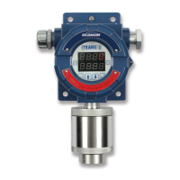
Describes the iTRANS-2 fixed gas monitor and its capabilities.
Lists the detailed technical specifications for the iTRANS-2 gas monitor.
Details the certifications and standards approved for the iTRANS-2.
Describes the cast aluminum housing, dimensions, and mounting features.
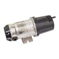
Details sensor housing, dimensions, accuracy, and protection class.
Explains the LED display and intrusive/non-intrusive input methods.
Information on connectors and jumpers for wiring and configuration.
Covers wall and column mounting methods for the gas monitor.
Guidance on optimal placement, height, and environmental factors for installation.
Steps for gathering wires and preparing the unit for wiring connections.
Details wiring connections for low, high, and fault alarm relays.
Instructions for connecting power supply and 4-20mA output signals.
Explains how to connect sensor heads to the main unit using specific wires.
Covers connecting the iTRANS-2 to digital controllers via Modbus RTU.
Final steps to complete wiring and power up the iTRANS-2 unit.
Describes the initial power-on sequence, sensor detection, and warm-up period.
How the monitor displays readings and identifies sensors in normal operation.
Introduces programming functions available via keypad and magnetic wand.
Details using a magnetic wand for sensor type, zeroing, calibration, and span adjustments.
Step-by-step guide for configuring alarms, time, and other settings using physical buttons.
Configuration for MX43 compatibility and Modbus communication setup.
Lists Modbus registers for accessing sensor data and instrument status.
Guidance on network termination resistors and jumper configuration for Modbus.
Information on sensor lifespan and recommended calibration frequency for accuracy.
Procedure for qualified personnel to replace a gas sensor.
Refers to operation section for zeroing and calibration procedures.
Table of common issues, their causes, and recommended solutions for the gas monitor.
Lists and explains device fault codes and programming function codes.
Details warranty periods for the iTRANS-2 products and sensors.
Outlines the manufacturer's limitations on warranty claims and liability.
Applicability and basic features of the HART interface for the iTRANS-2.
Specific hardware details for HART-supported iTRANS-2 units.
Wiring guidelines for HART communication and output signals.
Explains start-up, warm-up, normal, and fault modes for HART interface.
Lists and describes standard HART commands for device interaction.
| Output | 4-20 mA, HART, Modbus |
|---|---|
| Enclosure Rating | IP66/67 |
| Gas Type | Combustible, Toxic |
| Humidity | 0-95% RH (non-condensing) |
| Enclosure | Aluminum or Stainless Steel |
| Certifications | ATEX, IECEx |
| Detection Principle | Electrochemical, Infrared |
| Detection Range | Varies by sensor type |
| Output Signal | 4-20 mA |