iTRANS 2
FIXED POINT SINGLE OR DUAL GAS MONITOR
WITH DUAL ANALOG OUTPUTS
USER MANUAL
Revision 7.0
5 Operation
5.1 Initial Start-up
Once power is applied (12-28 VDC), the is operational. The LED display powers up, and
the system enters a start-up period. During this start-up period, the identifies the sensors
that are connected and then enters a three minute warm-up period.
5.2 Warm-up Period
During this warm-up period, the 4 20 mA outputs are limited
to 3 mA (16 mA for oxygen). After the three minute warm-up,
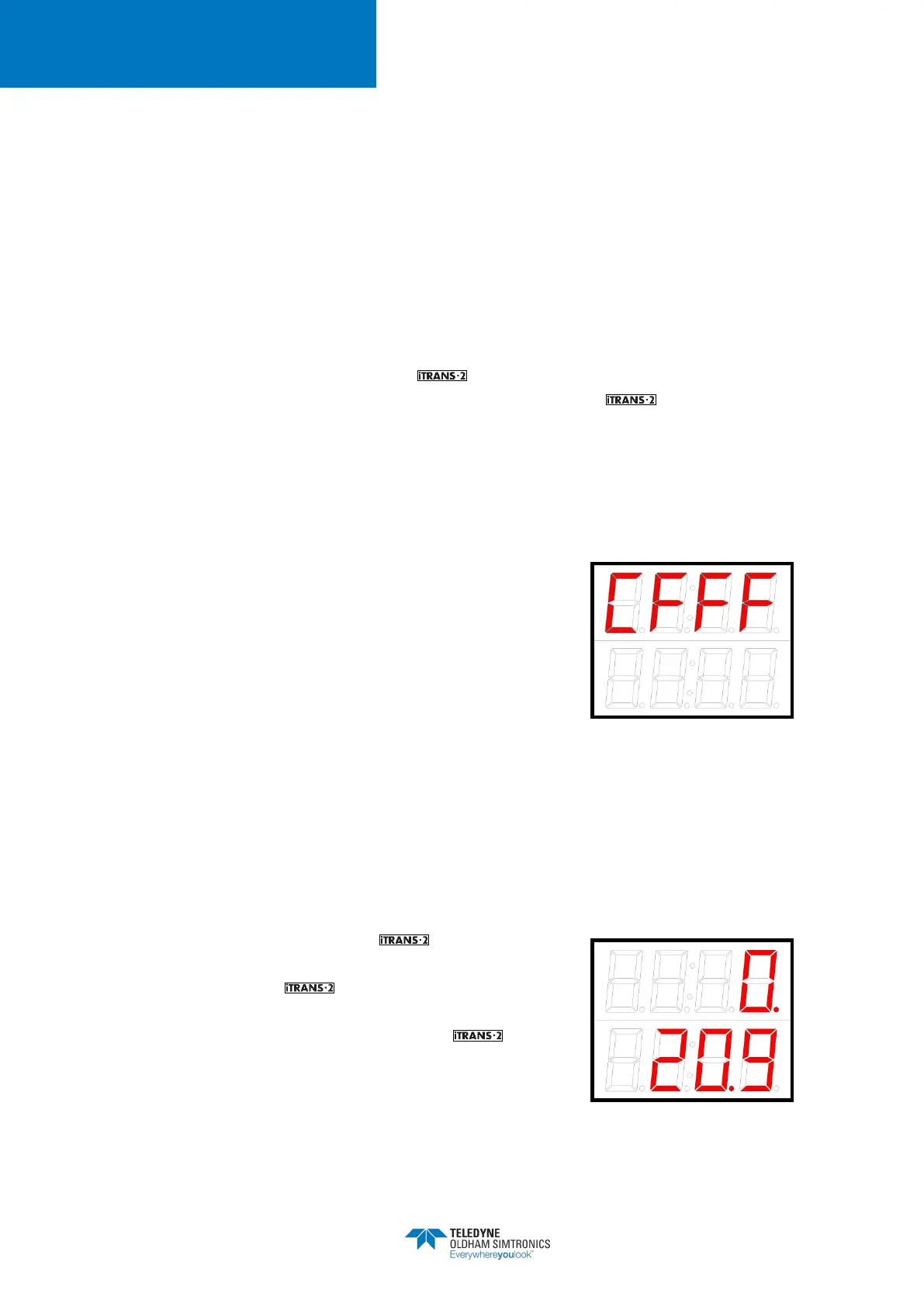
the unit will enter the Normal Operating Mode. If during the
warm-up period, the unit fails a self test, the display will show
a fault code, and the fault relay will be activated. Fault codes
are located in 8.
Figure 5-1 Sample Fault Code
Display
5.3 Normal Operating Mode
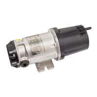
In Normal Operating Mode, the gas monitor will
display the instantaneous readings for each sensor wired into
the unit. The top of the display shows the gas reading
for Sensor 1. Sensor 1 should have the internal dip switches
set to 00 hex or 0F hex. The bottom row of the display
shows the gas reading for Sensor 2. Sensor 2 should have
the internal dip switches set to F0 hex.
Figure 5-2 Sample Dual-Sensor
Display