iTRANS 2
FIXED POINT SINGLE OR DUAL GAS MONITOR
WITH DUAL ANALOG OUTPUTS
USER MANUAL
Revision 7.0
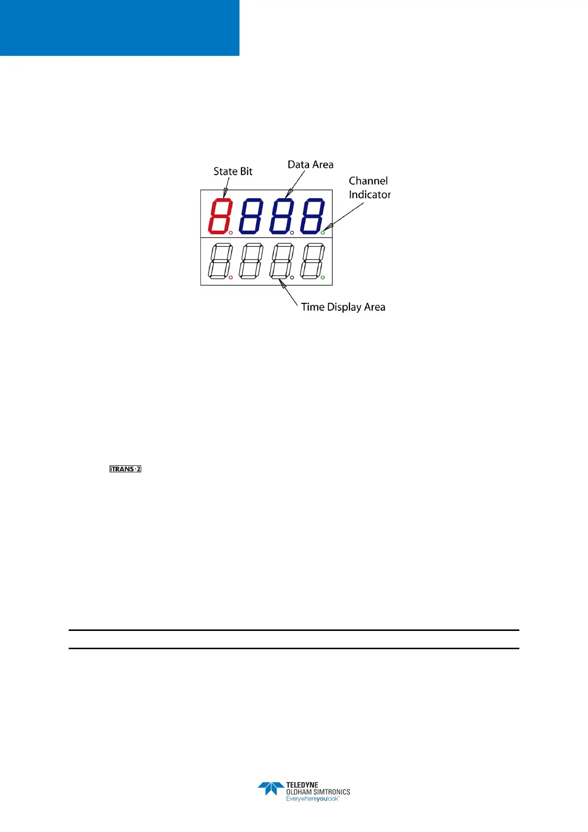
When in the Programming Mode, either via the magnetic wand or keypad operation, the top line
of the main display area shows a status bit and three data bits. The bottom line of the display
shows the timers (see Figure 5-5). The decimals on the far right of each line of the display are
channel indicators. The top decimal indicates channel 1 is being programmed, and the bottom
decimal indicates channel 2.
Figure 5-5 Components of the Display
5.5 Programming Mode – Non-intrusive Operation
5.5.1 Introduction
Non-intrusive calibration and programming is accomplished using a magnetic wand that comes
with the unit. Placing the magnetic wand over the embedded reed switches located under
the CH1 and CH2 designations (see Figure 5-4) of the faceplate will allow you to scroll through
menus and enter the desired function. The functions available through non-intrusive operation are
as follows.
• Sensor Type
• Zero
• Calibration
• Span Gas Value
• Span Reserve (in this order)
NOTE: Please see the 8 for a complete list of functions and function codes.