iTRANS 2
FIXED POINT SINGLE OR DUAL GAS MONITOR
WITH DUAL ANALOG OUTPUTS
USER MANUAL
Revision 7.0
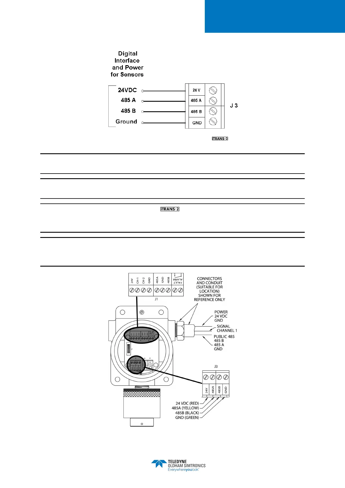
Figure 4-3 Sensor Connector J3 on the
NOTE: For dual-sensor configurations, place both of the same colored wires in the appropriate
terminal block and firmly tighten.
NOTE: Use #18 AWG (0.9 mm²) shielded cable for remote sensors. Maximum distance is 200
meters.
NOTE: When wiring remote sensors to the , “485 B” on J3 should be connected to “B-”
in the remote sensor enclosure, and “485 A” on J3 should be connected to “A+” in the remote
sensor enclosure.
NOTE: For remote or standalone sensors, there are four terminal blocks located in the remote
sensor housing. These terminal blocks are all tied together and follow the same wiring scheme
mentioned above.
Figure 4-4 Wiring Diagram for a Single On-board Sensor


 To Next Page