iTRANS 2
FIXED POINT SINGLE OR DUAL GAS MONITOR
WITH DUAL ANALOG OUTPUTS
USER MANUAL
Revision 7.0
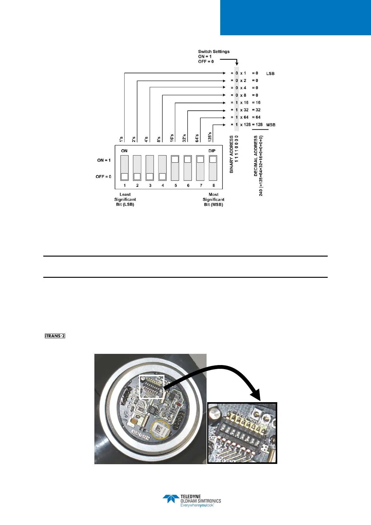
Figure 4-11 Setting the ModBus Address (Example Address of 240 Decimal)
4.6.3 Setting the ModBus Address for Stand-Alone Sensors
NOTE: This section is only necessary if you are connecting a sensor directly to a ModBus
controller, PLC, or digital system.
For stand-alone sensor heads used in a ModBus network, the address is set in the same manner.
Once the aluminum sensor head is removed with the sensor board, the sensor electronics module
is exposed. On the back of the sensor electronics module is a small 8-position DIP switch. The
address can be set from 10 to 255 in a similar manner as setting the ModBus address on the
except pin 8 on the sensor’s 8-position DIP switch is the least significant bit, and pin 1 is
the most significant bit.
Figure 4-12 Location of Address DIP Switch on Sensor Electronics Module