Model 300E Carbon Monoxide Analyzer
Instruction Manual
Getting Started
P/N 04288 REV: A 39
NOTE
Once you have completed the above set-up procedures, please fill out the
Quality Questionnaire that was shipped with your unit and return it to T-API.
This information is vital to our efforts in continuously improving our service and
our products.
THANK YOU.
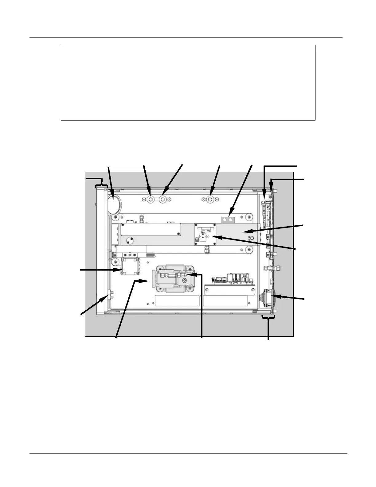
Particulate Filter
S
nc/Demod Board
GFC
Wheel/Motor
Assy
ON/OFF
SWITCH
PS1
+5 VDC
±15VDC
PS2
(+12 VDC)
Pum
Ass
Rela
Board
Optional
Zero/S
an
Valve
Sample
Chamber /
Optical
Bench
Critical Flow
Orifice
Front Panel
Rear Panel
CPU Card
Mother
Board
Power
Receptacle
Optional
Sample/Cal
Valve
Optional
Shutoff
Valve
Gas Flow
Sensor Assy
Optional
Zero
Scrubber
Figure 3–6: Assembly Layout





 To Next Page