Operating Instructions Model 300E Carbon Monoxide Analyzer
Instruction Manual
74 P/N 04288 REV: A
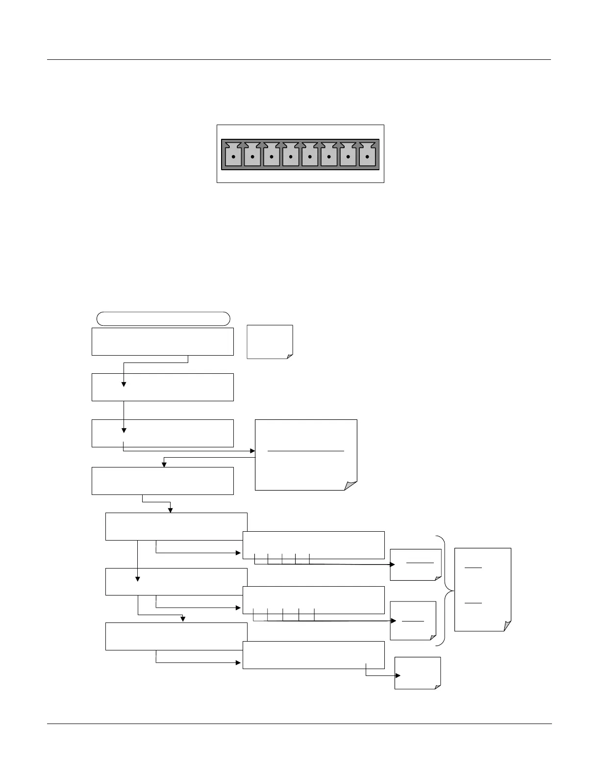
ANALOG
A1 A2 A3 A4
1 2 3 4 5 6 7 8
Figure 6–2: Analog Output Pin Assignments
6.5.1. Voltage Output Range Selection and Offset Adjustment
To select an output signal level or add a DC offset to one of the analyzer Analog
Output Channels press:
Calibrates Automatically
Exit to Return
to the main
Sample Display
DIAG ANALOG I / O CONFIGURATION
PREV NEXT ENTR EXIT
DIAG AIO AIN A/C FREQUENCY:
60 HZ
SET> EDIT EXIT
DIAG AIO AOUT CALIBRATED: NO
< SET SET> CAL EXIT
FROM ANALOG I/O CONFIGURATION MENU
Toggle these
Keys to set the
DC Offset
of the selected
channel
Exit to Return
to the I/O
Configuration
Menu
DIAG AIO
CONC_OUT
2 RANGE: 5V
SET> EDIT EXIT
DIAG AIO OUTPUT RANGE: 5V
0.1V 1V 5V 10V CURR ENTR EXIT
DIAG AIO CONC_OUT_2 REC OFS: 0 mV
< SET SET> EDIT EXIT
DIAG AIO
RECORD OFFSET: 0 MV
+ 0 0 0 0 ENTR EXIT
DIAG AIO
CONC_OUT_2 CALIBRATED: NO
<SET CAL EXIT
DIAG AIO CONC_OUT_2 CALIBRATED: YES
<SET CAL EXIT
These Keys set
the Signal Level
of the selected
channel
DIAG AIO CONC_OUT_2:5V, CAL
< SET SET>
EDIT
EXIT
Press
SET>
to select the Analog Output
channel to be configured:
DISPLAYED AS = CHANNEL
CONC_OUT_1 = A1
CONC_OUT_2 = A2
TEST OUTPUT = A3
Then Press EDIT to continue
Pressing ENTR
records
the new
setting and returns
to the previous
menu
Pressing EXIT
ignores
the new
setting and returns
to the previous
menu





 To Next Page