Model 300E Carbon Monoxide Analyzer
Instruction Manual
Operating Instructions
P/N 04288 REV: A 87
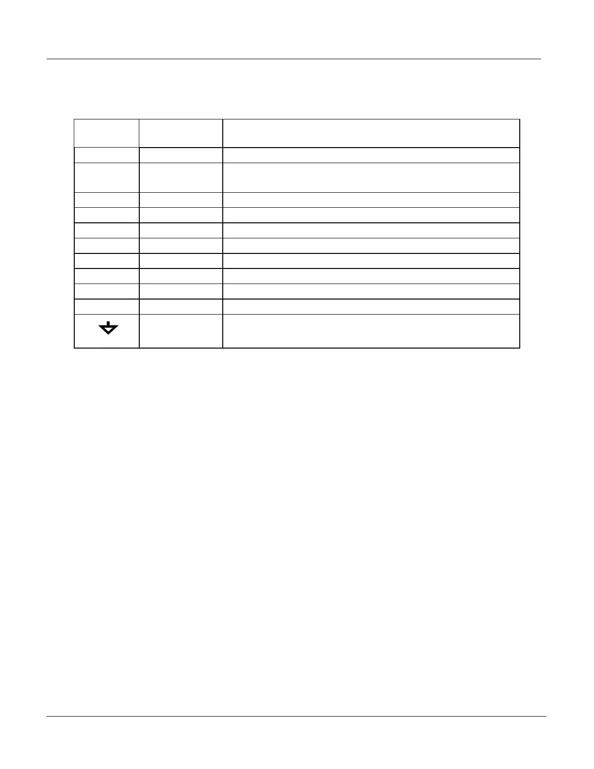
The pin assignments for the Status Outputs are:
Table 6–12: Status Output Pin Assignments
Output #
Status
Definition
Condition
1 SYSTEM OK On if no faults are present.
2
CONC VALID
On if CO concentration measurement is valid.
If the CO concentration measurement is invalid, this bit is OFF.
3 HIGH RANGE On if unit is in high range of DUAL or AUTO Range Modes.
4 ZERO CAL On whenever the instruments ZERO point is being calibrated.
5 SPAN CAL On whenever the instruments SPAN point is being calibrated.
6 DIAG MODE On whenever the instrument is in DIAGNOSTIC mode.
7 SPARE
8 SPARE
D
EMITER BUSS The emitters of the transistors on pins 1-8 are bussed together.
+ DC POWER + 5 VDC
Digital Ground
The ground level from the analyzer’s internal DC Power
Supplies.
6.7.2. Control Inputs
Several Control Inputs are provided via an 10-pin connector labeled CONTROL IN
on the analyzer’s rear panel. These are opto-isolated digital inputs that are
activated when a 5 VDC signal is applied to the “+” pin.
These inputs allow the user to remotely initiate Zero and Span calibrations. Two
methods for energizing the inputs is provided below; the first using the internal
+5V available on the CONTROL IN connector and the second, if an external,
isolated supply is employed.





 To Next Page