Operating Instructions Model 300E Carbon Monoxide Analyzer
Instruction Manual
72 P/N 04288 REV: A
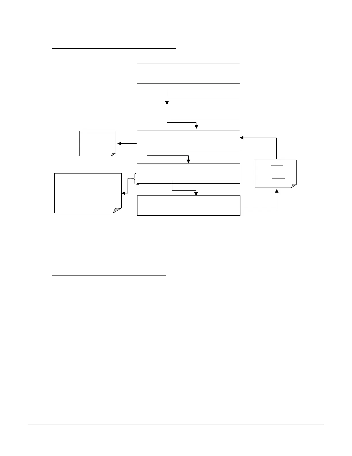
STEP 3: SET DILUTION RATIO FACTOR –
SAMPLE RANGE = 50.0 PPM CO =
< TST TST > CAL SETUP
SETUP C.3
CFG DAS
RNGE
PASS CLK MORE EXIT
SETUP C.3 RANGE CONTROL MENU
MODE SET UNIT
DIL
EXIT
DIL only appears
if the Dilution
Ratio Option has
been installed
SETUP C.3
DIL FACTOR: 1.0 GAIN
0 0 0 1 .0 ENTR EXIT
Toggle these keys to set the Dilution
Factor.
This is the number by which the
analyzer will multiply the CO
Concentration of the gas passing
through the Sample Chamber.
SETUP C.3
DIL FACTOR: 200.0 GAIN
0 0 2
0 .0
ENTR
EXIT
EXIT
ignores
the
new setting.
ENTR accepts
the
new setting.
The analyzer multiplies the CO concentration of the Sample gas passing through its
Sample Chamber by the Dilution Ratio Factor. If, for instance, the sample gas is
being diluted by a factor of 20:1, entering a Dilution Ration Factor of 20 would
provide the proper compensation.
STEP 4: CALIBRATE THE ANALYZER
- Once the above settings have been entered,
calibrate the instrument using one of the methods discussed in Section 7 of this
manual.
6.5. Analog Outputs - Electronic Configuration
The final step in configuring the analyzer’s four analog output channels is to set the
electronic signal type and range of each channel. This consists of selecting a type,
voltage or current, for A1 – A3 (if an optional current output driver has been
installed), and a signal level that matches the input requirements of the recording
device attached to the channel. A bipolar offset can be also added to the signal if
required.
In its standard configuration the analyzer Analog Outputs can be set for the
following DC voltage signal levels. Each range has is usable from -5% to + 5% of
the rated span.





 To Next Page