Optional Hardware and Software Model 300E Carbon Monoxide Analyzer
Instruction Manual
44 P/N 04288 REV: A
5.2.1. Zero/Span/Shutoff Valve Option 50
Filter
Pump
Sample
Chamber
Sample
Exhaust
Pressure Span
Vent Span
IZS
Zero/Span Valve
Sample/Cal Valves
O
tion 50
Shut Off ValveOrifice
Vent here if Input is Pressurized
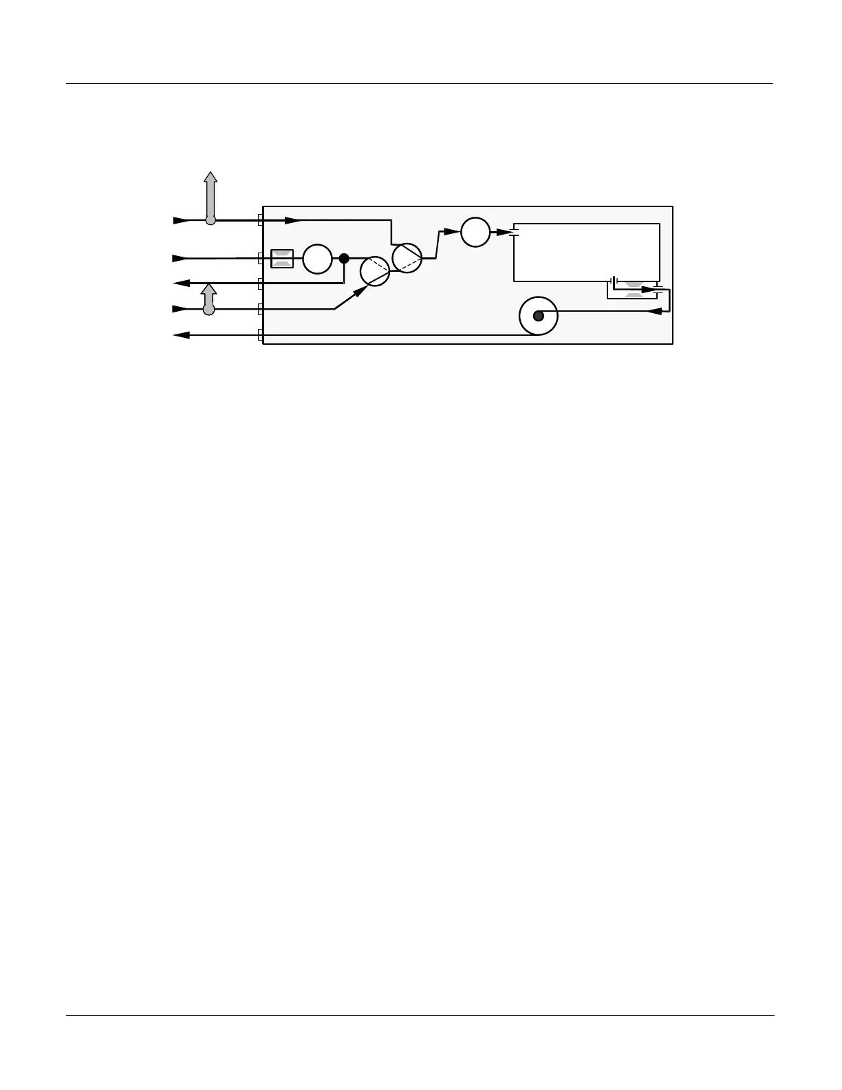
Figure 5–1: Pneumatic Diagram – Zero/Span/Shutoff Valves & Internal Zero
This option requires that both Zero Air and Span Gas be supplied from external
sources. It is specifically designed for applications where SPAN Gas will be supplied
from a pressurized bottle of calibrated CO gas. A flow control orifice, internal to the
instrument ensures that the proper flow rate is maintained. An internal vent line,
isolated by a shutoff valve ensures that the gas pressure of the SPAN gas is
reduced to ambient atmospheric pressure. Normally Zero Air would be supplied
from Zero Air Module such as a T-API model 701.
In order to ensure that SPAN gas does not migrate backwards through the vent line
and alter the concentration of the SPAN Gas, a gas line not less than 2 meters in
length should be attached to the Vent Span outlet on the Rear Panel of the
analyzer. To prevent the buildup of back pressure, this vent line should not be
greater than 10 meters in length.
The minimum SPAN Gas flow rate required for this option is 800 cc/min. The US
EPA recommends that the flow rate be at least 1600 cc/min. Regulating the
pressure of the gas bottle at 30 psig should produce the appropriate amount of
flow.
Table 5–1 lists the Open/Closed state of each valve during the analyzers various
operational modes.





 To Next Page