D Series Syringe Pumps
Section 6 Modifier Addition
6-4
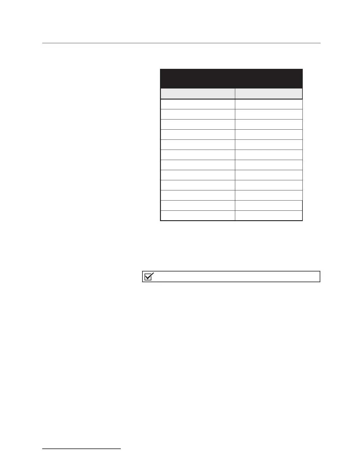
Table 6-2 contains modifier addition components for connecting
to a continuous flow system.
6.1.2 Modifier Mode Setup When first setting up a system for modifier mode, the pumps
should be zeroed and filled. To accomplish this, the pumps should
first be placed under independent control - constant pressure
mode.
Note
Once the modifier system is operating, the system does not
need to be zeroed before refilling.
1. If the pumps are running, press the STOP key once.
2. Press MENU > MORE (A).
3. Press 4 - MULTI-PUMP, to display the multi-pump menu.
4. Press 4 - INDEPENDENT to designate that the pumps be
operated under independent control. The number 4 will
blink, indicating that Independent Mode has been selected.
5. Press D - PREVIOUS, twice to return to the main menu.
6. Press CONST PRESS.
To zero the pumps 1. Place the pumps in independent control - constant pres-
sure mode, as detailed above.
2. Be sure the pumps are stopped.
3. Disconnect the inlet tubing from the inlet valve of pump A.
4. Select 2 pump independent control/constant pressure
mode. Refer to Section 5.6 Continuous Flow Mode.
Table 6-2 Modifier Addition Components
for Continuous Flow System
Description Part Number
Tee union fitting
1
16” 209-0169-47
Check valve cartridge 60-3864-010
Single check valve housing 60-1243-516
Tubing, check valve 60-1243-644
2-way valve -
1
8” OD 209-0098-05
Tubing, valve inlet 60-1243-658
Reduction union
1
8”to
1
16” 209-0162-10
Valve spacer 60-1243-659
1
16”OD 12 cm tubing 60-1243-540
1
8”OD x 2.57 SST tubing 60-1243-570
Check valve cartridge
1
8” 209-0161-80
Check valve/mixer tubing 60-1243-691
 Loading...