D Series Syringe Pumps
Appendix B Continuous Flow Introduction, Installation, and Operation for 30D
B-7
B.4 User Supplied Valves Users may also choose to supply their own valves. The following
information is necessary to choose the appropriate valves to work
with Teledyne Isco Continuous Flow software.
• Check valves
Do not use spring-loaded check valves if refilling at
atmospheric pressure; the pump seals are not designed to
draw against a vacuum.
• Powered valves
These are electrically triggered from the pump controller
and could be air or electrically actuated. Digital outputs
1-4 provide signals for control of four two-way valves. One
wire for each valve is connected to its specific connector on
the rear of the controller. A second wire for each valve
connects to ground. The signal provided is an open collector
which functions as a switch open for closure of the fluid
path. A switch closure (low) signals opening of the fluid
path.
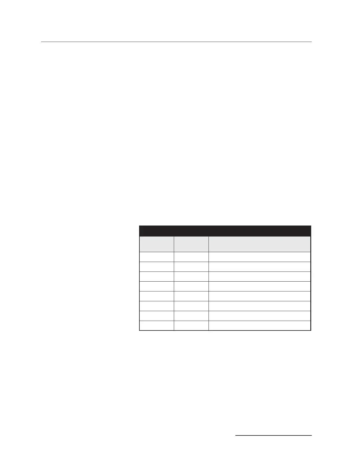
Table B-3 shows the relationship between the digital output,
pump valve location, and the fluid path status for the ACCESS
CTRL connections. Refer to the accessory control connections on
the rear panel of the pump controller.
Alternate connections can be made to drive low power 12-15 V
relays or electric valves. Assume two wires per relay or valve.
The first wire is connected to the appropriate digital output on
the back of the pump controller. The second wire can be con-
nected to the +15 V connector, to supply a maximum of 200 mA
for switching of relays or valves. Observe correct polarity if the
valve or relay is polarized.
Table B-3 Accessory Control Digital Outputs
Digital
Output
Pump Valve
Location
Fluid Path Status
1 A Inlet (open or closed)
2 A Outlet (open or closed)
3 B Inlet (open or closed)
4 B Outlet (open or closed)
5 C Inlet (open or closed)
6 C Outlet (open or closed)
7 D Inlet (open or closed)
8 D Outlet (open or closed)



 To Next Page