D Series Syringe Pumps
Section 1 Introduction
1-18
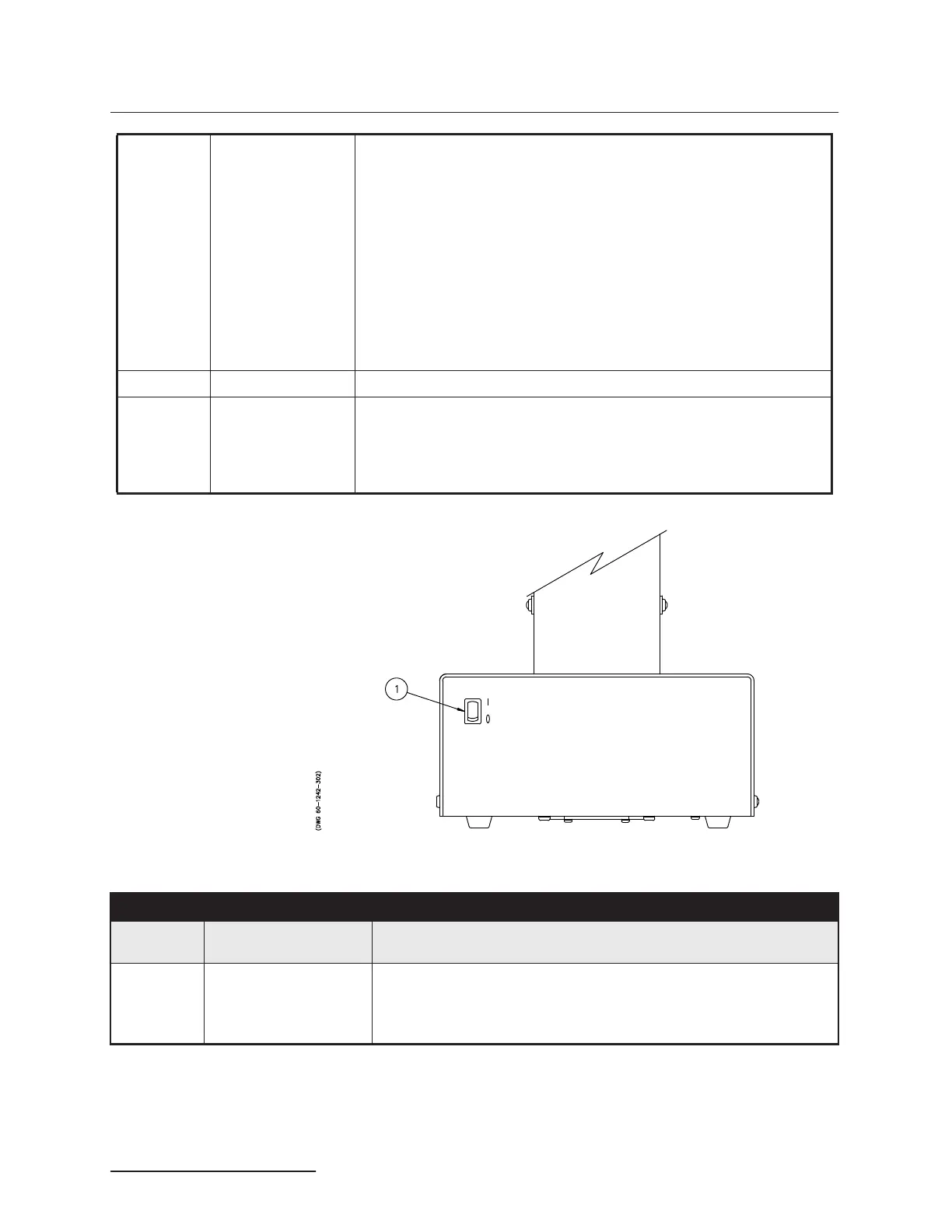
Figure 1-8 Pump front panel controls
1.5 Electrical Connections The pump controller may be placed on top of the pump, or
wherever safety and convenience dictate. Power is supplied to
the pump controller through the control cable.
6 External Fuses * Limits pump current drawn from main power supply.
Replace with same type: (“T” time delay fuses)
1 - 2.0 Amp for 100/117 volt operation
2 - 1.0 Amp for 234 volt operation
For 500HPx Pumps:
1 - 7.5 Amp for 100 volt operation
1 - 6.25 Amp for 117 volt operation
2 - 3.2 Amp for 234 volt operation
For 30D Pumps:
1 - 3.2 Amp for 100/117 volt operation
2 - 1.6 Amp for 234 volt operation
To remove, rotate cap counterclockwise.
7 Chassis ground Ground point for high static installations.
* Internal fuses not
replaceable by the
operator
F101 4.0 Amp “T”
F102, F104 1.5 Amp “T”
F103 0.75 Amp “T”
For 500HPx/30D
F101 6.25 Amp “T”
Table 1-14 Pump Front Panel
Item No. on
Figure 1-8
Connector Description
1 Mains power switch Disconnects power from the pump circuits for setup changes, such as
connecting the controller.
“1” = mains power is applied to the pump circuitry.
“0” = mains power is removed from the pump circuitry.