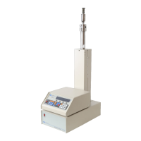
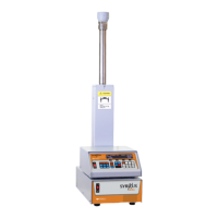
D Series Syringe Pumps
Section 1 Introduction
1-19
CAUTION
All connections between the pump and controller should be
made BEFORE the pump is connected to mains power.
1. Connect the pressure transducer cable (which originates
from the top of the pump cylinder) to the nine pin sub-D
PRESSURE TRANSDUCER connector on the pump rear
panel (Figure 1-7). Be sure to tighten the thumbscrews.
2. Connect the control cable (which originates from the first
or only pump rear panel) to the PUMP A connector on the
rear panel of the controller (Figure 1-6), and tighten the
thumbscrews. This cable must be plugged into the PUMP
A connector.
Note
There are four PUMP connectors on the rear of the controller.
Only the PUMP A connector is wired to supply power to the
controller; therefore, one pump must be attached to this con-
nector.
3. Check the serial number tag to make sure the voltage rat-
ing of the pump is correct.
4. Connect the line cord to the MAINS connector on the back
of the pump.
1.5.1 Cabling For all systems, connect the control cable of the pump module
(Pump A for multiple-pump systems) to the connector labeled
PUMP A on the rear panel of the controller. Subsequent pumps in
multiple-pump systems can be connected to controller connectors
PUMP B, PUMP C, and PUMP D.
Note
The transducer cable (refer to Figures 1-9 and 1-10) must be
plugged into the PRESSURE TRANSDUCER connector on the rear
panel of the pump module for the pump to operate.
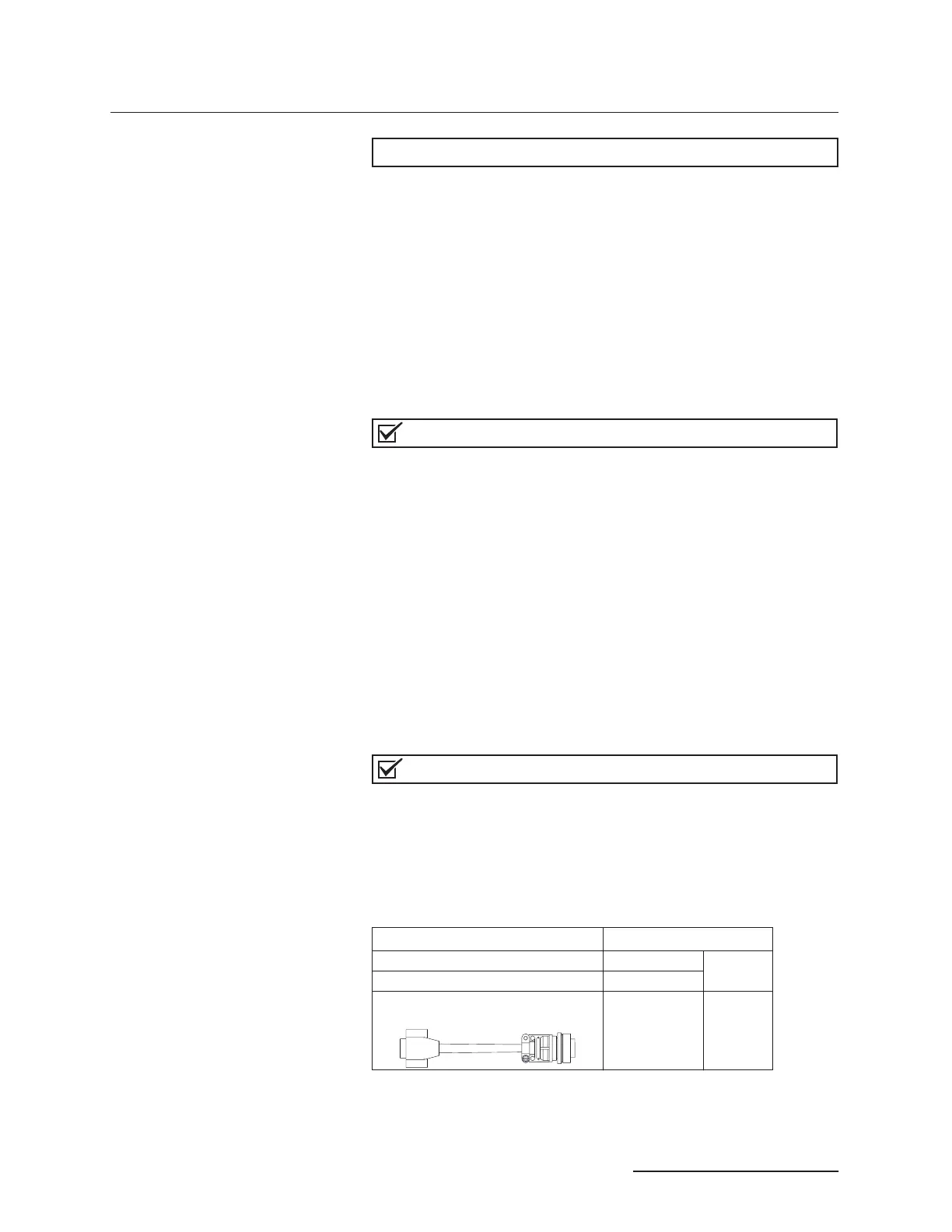
Cable part numbers and lengths are listed in the following chart:
USB and TCP/IP use cable package 60-1247-168.
Pump controller connect cable (see Figure 1-10). 7 ft (2.1m)
(attached to
pump)
Pump module transducer cable (see Figure 1-9). 4 ft (1.2m)
30D/65D Pump module transducer cable
4.5 ft (1.4 m) 69-1244-413
 Loading...