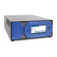
UDB-9000 Universal Deck Box - UDB-9000-M (Portable) and UDB-9000-MR (Rack Mount) Configurations 1-7
1 Overview Connections
Connections
All of the connections to the UDB-9000 are made on the front panel of the
portable configuration and the rear panel of the rack mount configuration.
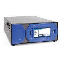
Connections—Portable Configuration
The connections to the portable configuration of the UDB-9000 are shown in
Figure 1-2 on page 1-5. They include the following:
PWR: 5-pin bulkhead connector—connects to the AC
power source.
XDCR: 12-pin bulkhead connector—connects to the
transducer.
AUX: 15-pin bulkhead connector—available for
connection to headphones and to external 10–30
VDC power (optional). Also provides spare outputs
and inputs and a transmit sync output.
COM1: DB-9S connector—female serial port connector
that connects to a PC and is used for sending and
receiving acoustic telemetry modem commands
and data.
COM2: DB-9S connector—female serial port connector
that connects to a PC and is used for inputting
commands and outputting round trip travel times
and status information in a manner that emulates
the DS-7000 Acoustic Deck Set.
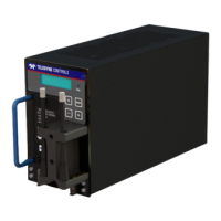
Connections—Rack Mount Configuration
The connections to the rack mount configuration of the UDB-9000 are shown
in Figure 1-4. They include the following:
PWR: 5-pin bulkhead connector—connects to the AC
power source.
XDCR: 12-pin bulkhead connector—connects to the
transducer.

 Loading...