UDB-9000 Universal Deck Box - UDB-9000-M (Portable) and UDB-9000-MR (Rack Mount) Configurations 3-7
3 Installation and Setup Deploying the Transducer
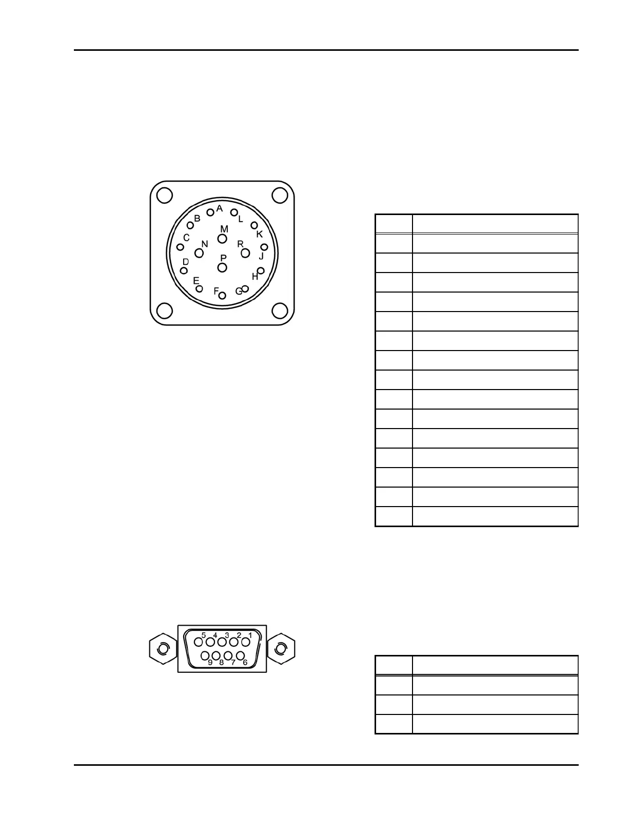
3. If using a headphone set, externally triggering the transmitter or
connecting the binary inputs and outputs, make these connections using
the AUX connector. An AUX cable is optionally available. Refer to
Figure 3-6 for the connector pin orientation, and to Table 3-3 for the
pinout information.
4. If sending DS-7000 commands and receiving round trip travel times and
status information, connect the serial port of a PC to the COM2
connector. Refer to Figure 3-7 for the connector pin orientation, and to
Table 3-4 for the pinout information.
Figure 3-6 AUX
Connector
Table 3-3 AUX Connector
Pinouts
PIN DESCRIPTION
A Open Collector In 0
B NC
C Headphone L
D Headphone R
E Headphone Shield
F Output Signal Ground
G Open Collector Out 1
H Open Collector Out 0
J Transmit Sync/Silent Ping Out
K Input Signal Ground
L Open Collector In 1
M 10-30VDC Power In (+)
N 10-30VDC Power In (+)
P 10-30VDC Power Return (-)
R 10-30VDC Power Return (-)
Figure 3-7 COM2
Connector
Table 3-4 COM2 Connector
Pinouts
PIN DESCRIPTION
2 Tx
3 Rx
5 Ground

 Loading...