3-8 TELEDYNE BENTHOS
User’s Manual P/N M-270-10, Rev. B
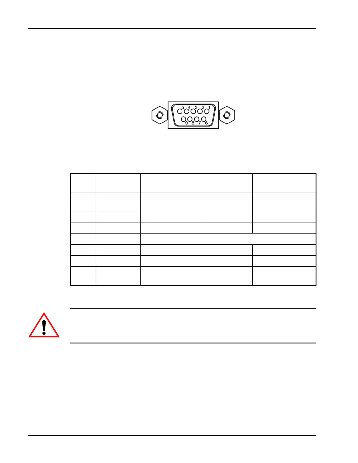
5. If sending and receiving acoustic telemetry modem commands and
data, connect the serial port of a PC to the COM1 connector. Refer to
Figure 3-8 for the connector pin orientation, and to Table 3-5 for the
pinout information.
Figure 3-8 COM1 Connector
Table 3-5 COM1 Connector Pinouts
PIN LABEL DESCRIPTION
SIGNAL
DIRECTION
2 TXD/RX(-) RS-232 Transmit/RS-422 Receive(-)
Modem to Host/
Host to Modem
3 RXD RS-232 Receive Host to Modem
4 TX(+) RS-422 Transmit(+) Modem to Host
5 GND Common Ground
6 TX(-) RS-422 Transmit(-) Modem to Host
7 CTS Clear to Send Host to Modem
8 RTS/RX(+) Request to Send/RS-422 Receive(+)
Modem to Host/
Host to Modem
WARNING When disconnecting the deck box, do not pack any cables
inside the UDB-9000 case, as doing so may damage the touch screen
display.

 Loading...