50 MA365 • Rev. A2
Tellabs
®
6325 Edge Node 3 Reference Information
Power system
description
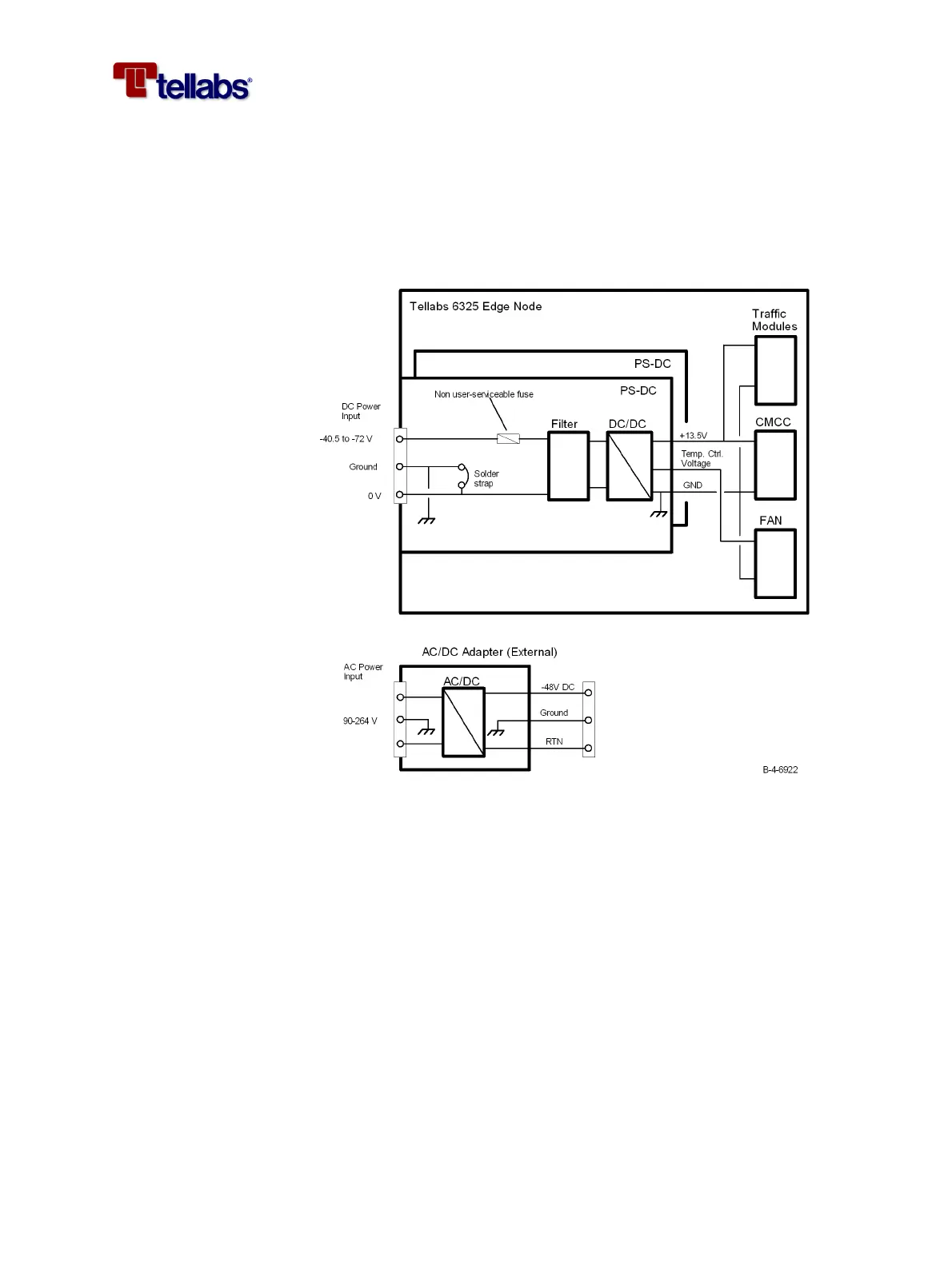
The following figure shows the power system of the Tellabs 6325 node. The
Tellabs 6325 node may house two PS-DC modules, each capable of providing
full power to the node. This allows for power supply protection. Each PS-DC
module has one DC power input, therefore two PS-DC modules must be used
if supply protection is needed. If AC powering is needed then the external
AC/DC adapter must be used. The external AC/DC adapter provides -48 V
DC to the input of the PS-DC module installed in the Tellabs 6325 node.
The AC/DC adapter may be connected to any distribution system, TN, TT or
IT.
With a soldered strap inside the PS-DC module it is possible to select between
DC-C (0 V connected to ground) or DC-I (0 V separated from ground) ground-
ing of the Tellabs 6325 node. Default is DC-C shown on the figure.
Power supply
configurations
The Tellabs 6325 node may be powered from an AC input or DC input. The
customer can choose between the following configurations:
• AC input only. This may be the case in many non telecommunications of-
fices. Protection requires extra set of PS-DC module and AC/DC adapter.
• Combined AC and DC powering. AC input as main supply and a DC in-
put as protection supply (extra PS-DC module required) in case the AC
supply fails.
• DC input only. One DC input as main power supply and another DC in-
put (extra PS-DC module required) as protection supply in case the main
supply fails.