MA365 • Rev. A2 25
Tellabs
®
6325 Edge Node 2 Installation Information
2.5 Installing the Modules
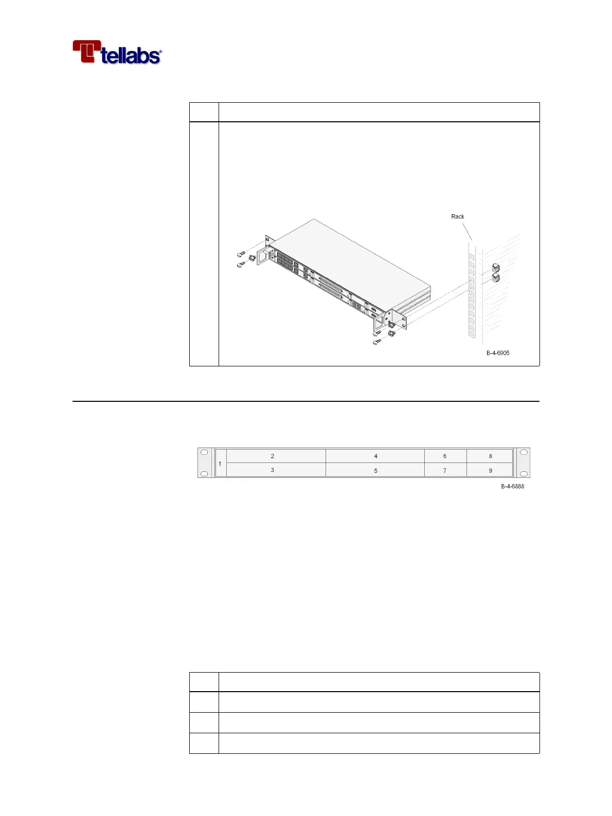
Slots in the Tellabs 6325
node subrack
The SC2 subrack comprises 9 slots for modules.
To install the support
modules
Follow this procedure to install the support modules required in any configu-
ration.
Warning: If you are going to remove a module from a working Tellabs 6325
node then remember to follow the instructions in ‘2.8 Removing a
Module from the Subrack’ on page 37.
Warning: Make sure to fasten the PS-DC modules with the screws as described
in this procedure.
Note: To avoid damage on components sensitive to static electricity, use an
antistatic bracelet connected to the chassis of the Tellabs 6325 node.
Note: When installing the modules, care should be taken in order not to
bend/destroy the EMC gaskets on the front mechanics.
3 Install the Tellabs 6325 node in the desired rack position. Fasten it
with four M6 screws including protection rings.
Note: The screw at the top left of the unit must be mounted without
a protection ring, to ensure firm contact to safety earth.
Note: Make sure that the subrack brackets are installed on unpainted
rack area.
Step Action
Step Action
1
Install the Fan module in slot 1
2 Install the CMCC module in slot 7
3 Install a PS-DC module in slot 9