56 MA365 • Rev. A2
Tellabs
®
6325 Edge Node 3 Reference Information
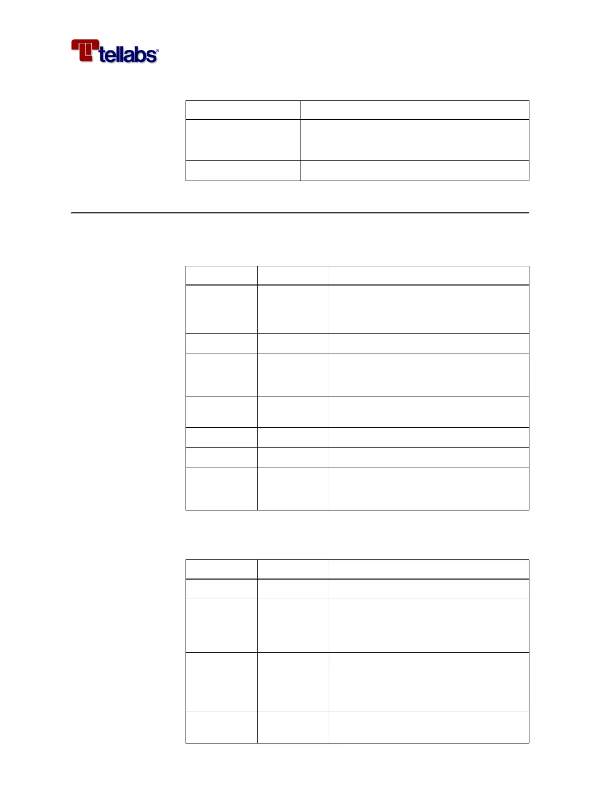
3.5.3 Synchronization Interface
External 2 MHz
reference timing source
The following table shows the specifications for the external 2 MHz synchro-
nization input at reference point ER.
2 MHz output port The following table shows the specifications for the external 2 MHz synchro-
nization output at reference point ES.
Peak voltage mark • 2.37 V
P
+/- 10% (Coaxial pair - 75 Ohm)
• 3.00 V
P
+/- 10% (Symmetrical pair - 120 Ohm)
Pulse shape Table 6 /G.703, Figure 15 /G.703
Parameter Value for 2 Mbit/s tributary output ports
Parameter Reference Value for 2 MHz synchronization input port
Input imped-
ance
G.703 • 120 Ohm
• High impedance (>1.6 kOhm with par-
allel capacity < 60 pF)
Frequency 2.048 MHz +/- 20 ppm (as output)
Jitter and
Wander toler-
ance
EN 300 462-5 Figure 2 and 3
Over voltage
protection
G.703 ITU-T K.20
Return loss G.703 >15 dB @ 2.048 MHz
√f attenuation G.703 6 dB @ 2.048 MHz
Grounding of
outer conduc-
tor or screen
G.703 Always connected to ground
Parameter Reference Value for 2 MHz synchronization output port
Frequency 2.048 MHz +/- 20 ppm
Mask Figure 21/
G.703
FTZ TL 5805-
3170
2.4 - 3.6 V
PP
Jitter
Wander
Table 10/
G.703
Figure 1/EN
300 462-5
0.05 UI
PP
@ 20 Hz - 100 kHz
Over voltage
protection
G.703 ITU-T K.20