The ability to set arbitrary values into simple display devices is not needed in typical design
activities. However, it gives users a simple mechanism for verifying that these devices are
functioning correctly in case a malfunction is suspected. Thus, it can be used for troubleshooting
purposes.
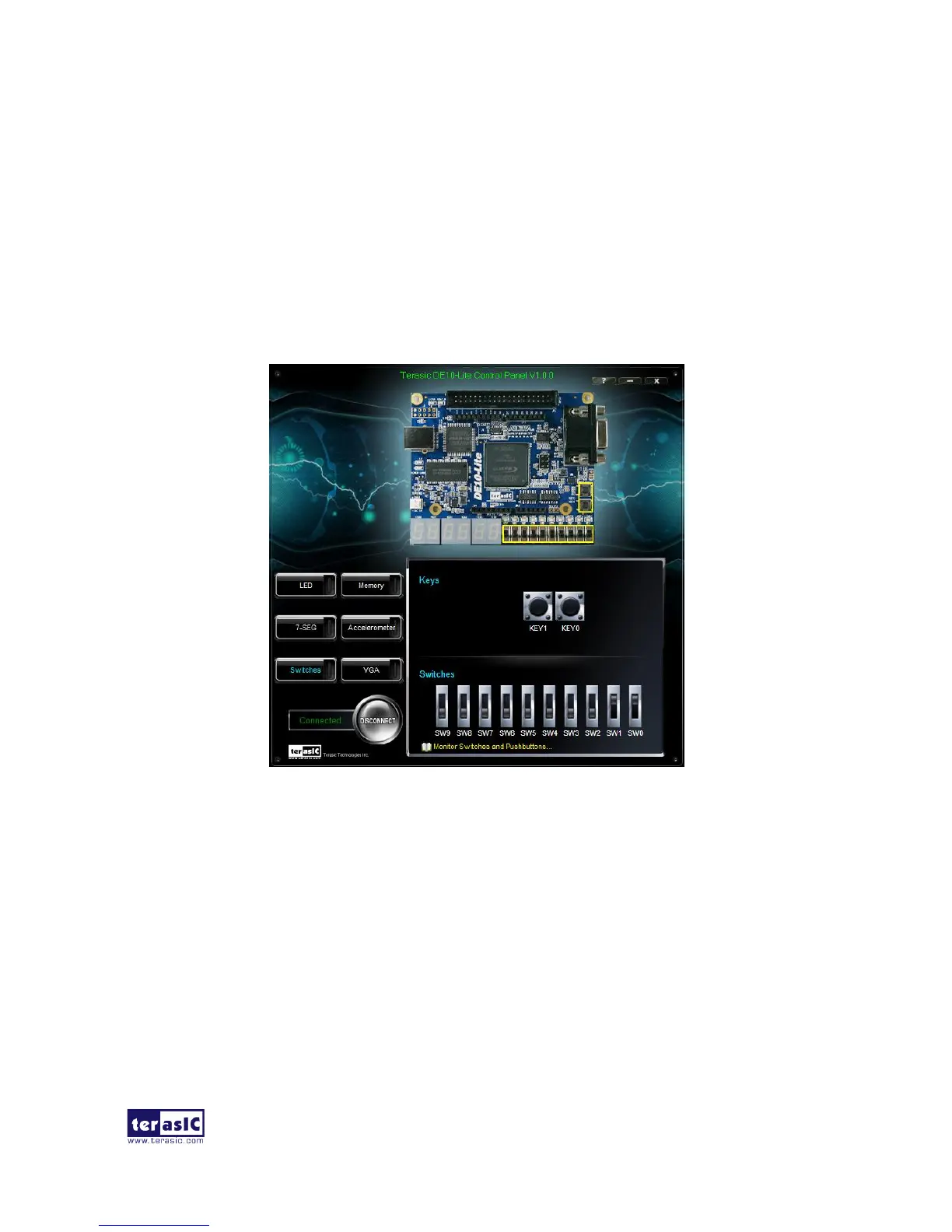
Choosing the Switches tab leads you to the window in Figure 2-5. The function is designed to
monitor the status of slide switches and push buttons in real time and show the status in a graphical
user interface. It can be used to verify the functionality of the slide switches and push-buttons.
Figure 2-5 Monitoring switches and buttons
The ability to check the status of push-button and slide switch is not needed in typical design
activities. However, it provides users a simple mechanism to verify if the buttons and switches are
functioning correctly. Thus, it can be used for troubleshooting purposes.
The Control Panel can be used to write/read data to/from the SDRAM chips on the DE10-Lite board.
As shown below, we will describe how the SDRAM may be accessed; Click on the Memory tab and
select “SDRAM” to reach the window in Figure 2-6.
 Loading...