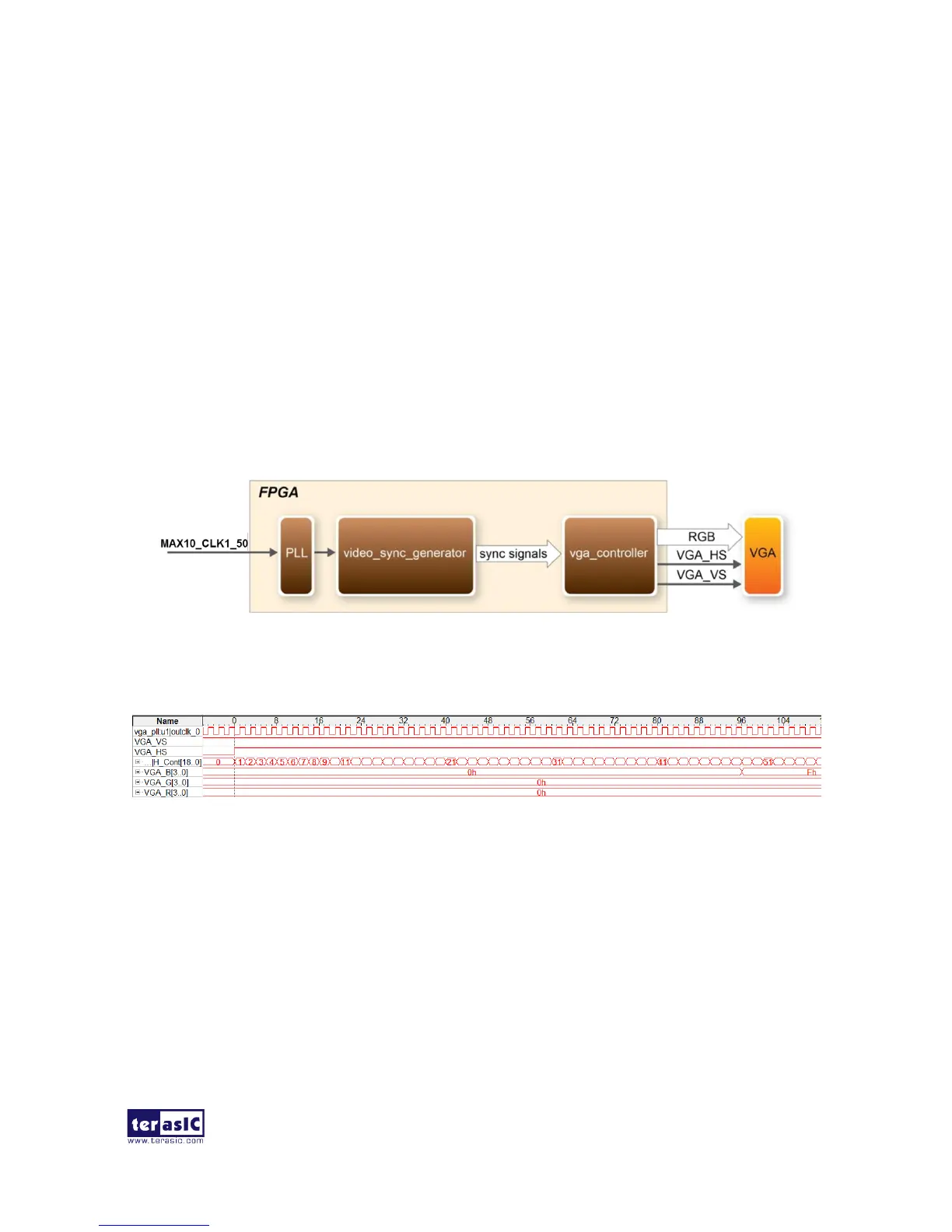
This demonstration displays a simple blue, red and green color pattern on a VGA monitor using the
VGA output interface on DE10-Lite board. Figure 5-5 shows the block diagram of the design.
The major block called video_sync_generator generates the VGA timing signals, horizontal
synchronization, vertical synchronization and blank in standard VGA resolution (640x480 pixels, at
25 MHz).
These signals will be used in vga_controller block for RGB data generation and data output. Please
refer to the chapter 3.8 in DE10-Lite_User_Manual on the DE10-Lite System CD for detailed
information of using the VGA output.
As shown in Figure 5-6, the RGB data drives each pixel in turn across the row being displayed
after the time period of back porch.
Figure 5-5 Block diagram of the VGA Pattern demonstration
Figure 5-6 Timing Waveform of VGA interface