This demonstration shows how to use the FPGA on-die ADC to measure the input power voltage
from the six analog input pins among the Arduino connector. The measured voltage is displayed on
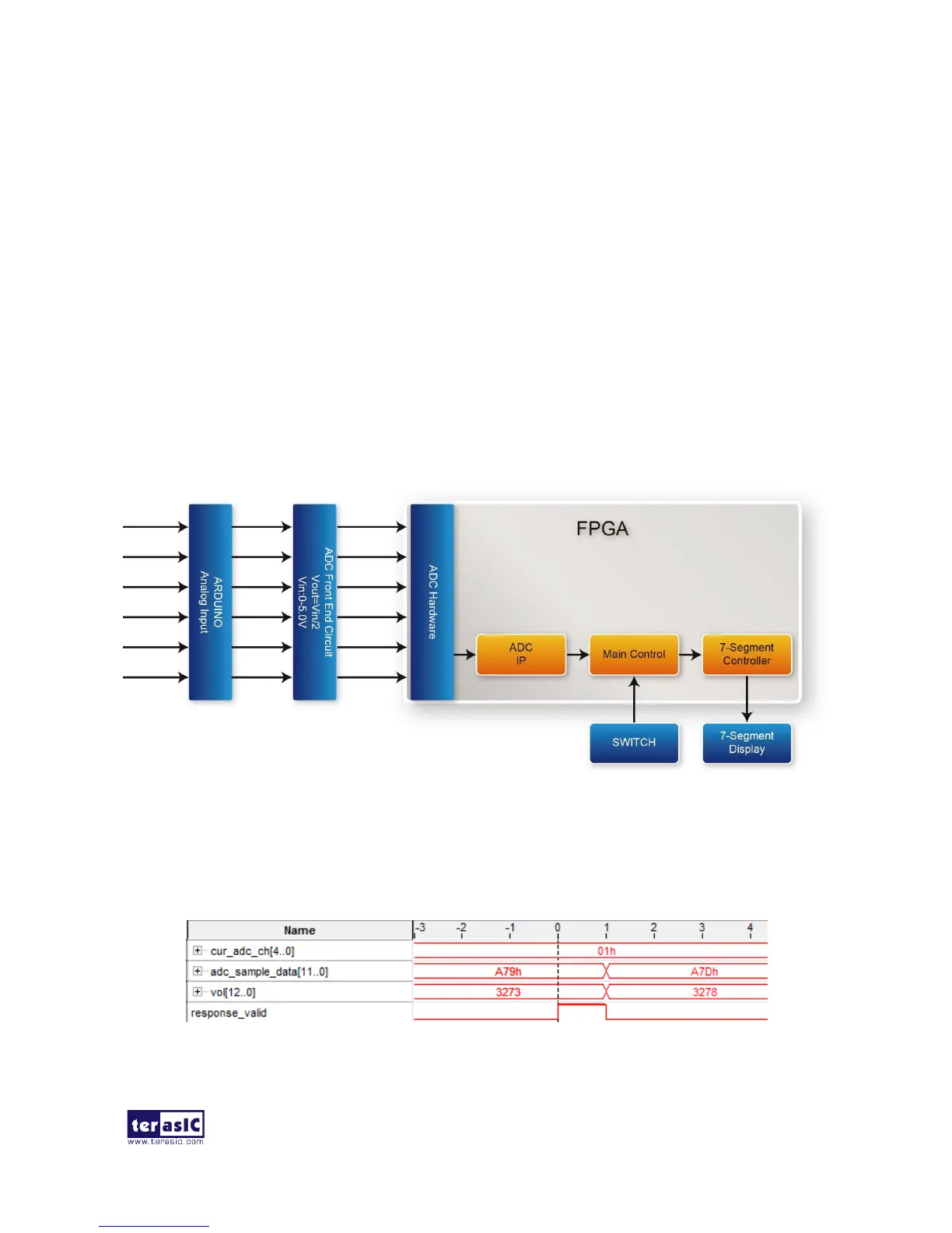
the six 7-segment display. Figure 5-9 shows the block diagram of this demonstration. The main
control uses the Altera ADC IP to retrieve the 12-bit digitalized analog value according the channel
specified by the SWITCH on the DE10-Lite. The input voltage can be calculated based on the
12-bit digital value. Finally, the voltage value will be display on the 7-segment display by using the
7-segment controller.
The 12-bit represents 0~2.5V input voltage to the ADC hardware. In the ADC front-end circuit, the
output voltage is half of the input voltage. So the input voltage to the ARDUINO analog input can
be calculated with the formula listed below:
VOLinput= (12-bit integer value)/4095 x 2.5 x 2 = (12-bit integer value)/4095 x 5.0
Figure 5-9 Block diagram of the ADC measurement demonstration
In the demonstration, a Signal Tap is also provided to display the retrieved 12-bit digitalized value
and the calculated voltage for the input power to the ARDUINO analog input as shown in Figure
5-10.
Figure 5-10 Signal Tap of ADC


 To Next Page