EasyManua.ls Logo

Terasic DE10-Lite - 3.3 User Input;Output Devices

Terasic DE10-Lite
75 pages
Print Icon
To Next Page IconTo Next Page
To Previous Page IconTo Previous Page
Loading...
DE10-Lite
User Manual
25
www.terasic.com
May 11, 2018
3
3
.
.
3
3
U
U
s
s
i
i
n
n
g
g
t
t
h
h
e
e
P
P
u
u
s
s
h
h
-
-
b
b
u
u
t
t
t
t
o
o
n
n
s
s
,
,
S
S
w
w
i
i
t
t
c
c
h
h
e
e
s
s
a
a
n
n
d
d
L
L
E
E
D
D
s
s
User-Defined Push-buttons
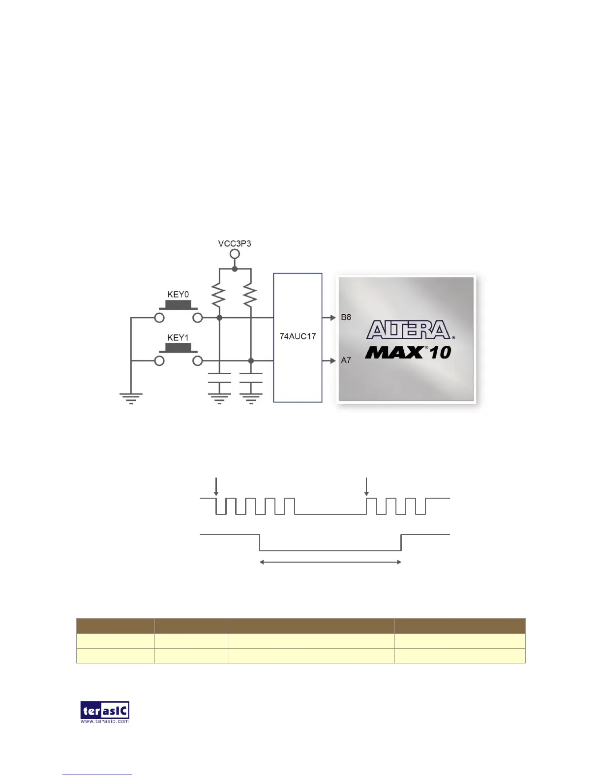
The board includes two user defined push-buttons that allow users to interact with the MAX 10
FPGA device. Each of these switches is debounced using a Schmitt Trigger circuit as indicated in
Figure 3-13. A Schmitt trigger feature introduces hysteresis to the input signal for improved noise
immunity, especially for signal with slow edge rate and act as switch debounce in Figure 3-14 for
the push-buttons connected. Table 3-3 list the pin assignment of user push-buttons.
Figure 3-13 Connections between the push-button and MAX 10 FPGA
Figure 3-14 Switch debouncing
Table 3-3 Pin Assignment of Push-buttons
Signal Name
FPGA Pin No.
Description
I/O Standard
KEY0
PIN_B8
Push-button[0]
3.3 V SCHMITT TRIGGER"
KEY1
PIN_A7
Push-button[1]
3.3 V SCHMITT TRIGGER"
Pushbutton releasedPushbutton depressed
Before
Debouncing
Schmitt Trigger
Debounced

Related product manuals