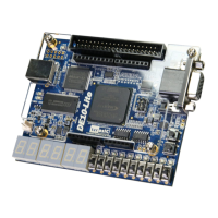
The board comes with a digital accelerometer sensor module (ADXL345), commonly known as
G-sensor. This G-sensor is a small, thin, ultralow power assumption 3-axis accelerometer with
high-resolution measurement. Digitalized output is formatted as 16-bit in two’s complement and
can be accessed through SPI (3- and 4-wire) and I2C digital interfaces.
With GSENSOR_CS_N signal to high, the ADXL345 is in I2C mode. With the GSENSOR_SDO
signal to high, the 7-bit I2C address for the device is 0x1D, followed by the R/W bit. This translates
to 0x3A for a write and 0x3B for a read. An alternate I2C address of 0x53 (followed by the R/W bit)
can be chosen by low the GSENSOR_SDO signal. This translates to 0xA6 for a write and 0xA7 for
a read.
More information about this chip can be found in its datasheet, which is available on manufacturer’s
website or in the directory \Datasheet\G-Sensor folder of DE10-Lite system CD.
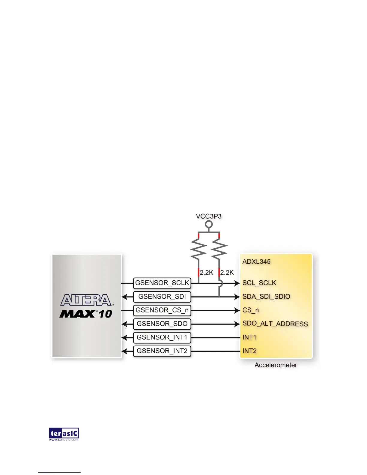
Figure 3-24 shows the connections between the accelerometer sensor and MAX 10 FPGA. Table
3-13 lists the pin assignment of accelerometer to the MAX 10 FPGA.
Figure 3-24 shows the connections between the accelerometer sensor and MAX 10 FPGA.
 Loading...