There are two types of configuration method supported by DE10-Lite:
1. JTAG configuration: configuration using JTAG ports.
JTAG configuration scheme allows you to directly configure the device core through JTAG pins -
TDI, TDO, TMS, and TCK pins. The Quartus II software automatically generates .sof files that are
used for JTAG configuration with a download cable in the Quartus II software program.
2. Internal configuration: configuration using internal flash.
Before internal configuration, you need to program the configuration data into the configuration
flash memory (CFM) which provides non-volatile storage for the bit stream. The information is
retained within CFM even if the DE10-Lite board is turned off. When the board is powered on, the
configuration data in the CFM is automatically loaded into the MAX 10 FPGA.
◼ JTAG Chain on DE10-Lite Board
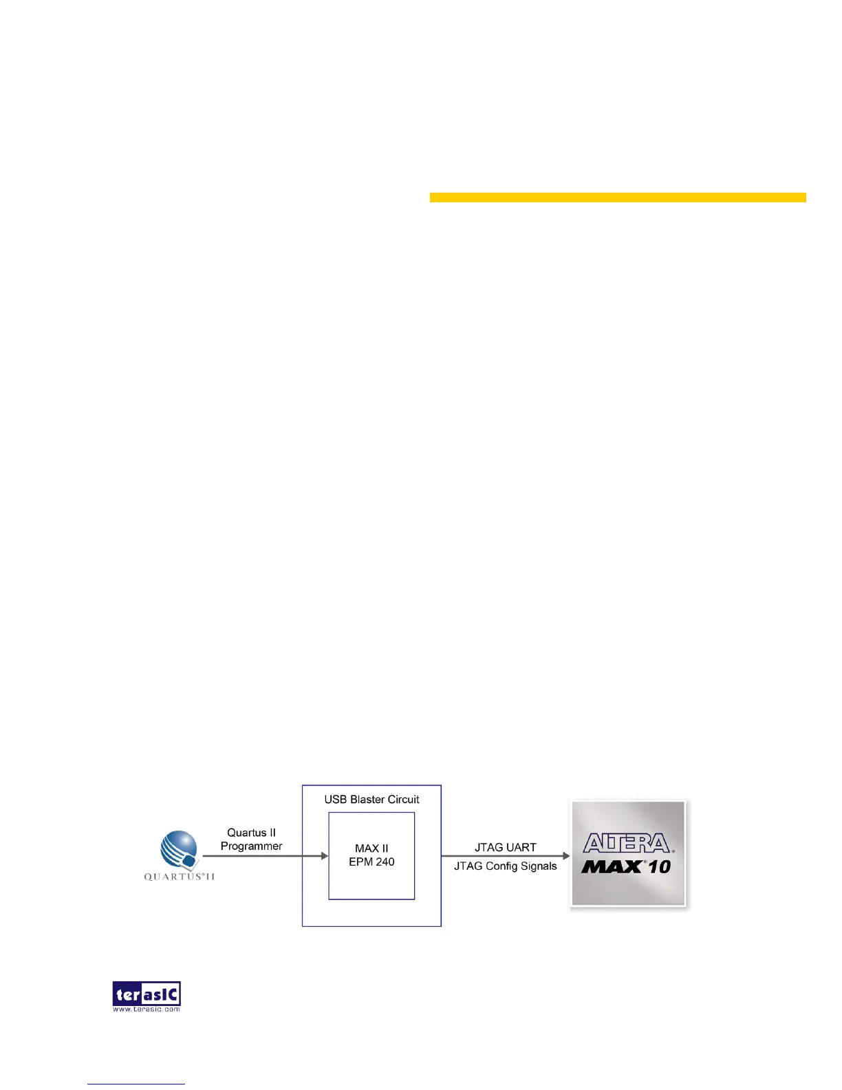
The FPGA device can be configured through JTAG interface on DE10-Lite board, but the JTAG
chain must form a closed loop, which allows Quartus II programmer to the detect FPGA device.
Figure 3-1 illustrates the JTAG chain on DE10-Lite board
Figure 3-1 The JTAG configuration scheme
 Loading...