This demonstration illustrates how to use the digital accelerometer on the DE10-Lite board to
measure the static acceleration of gravity in tilt-sensing applications. As the board is tilted from left
to right and right to left, the digital accelerometer detects the tilting movement and displays it on the
LEDs.
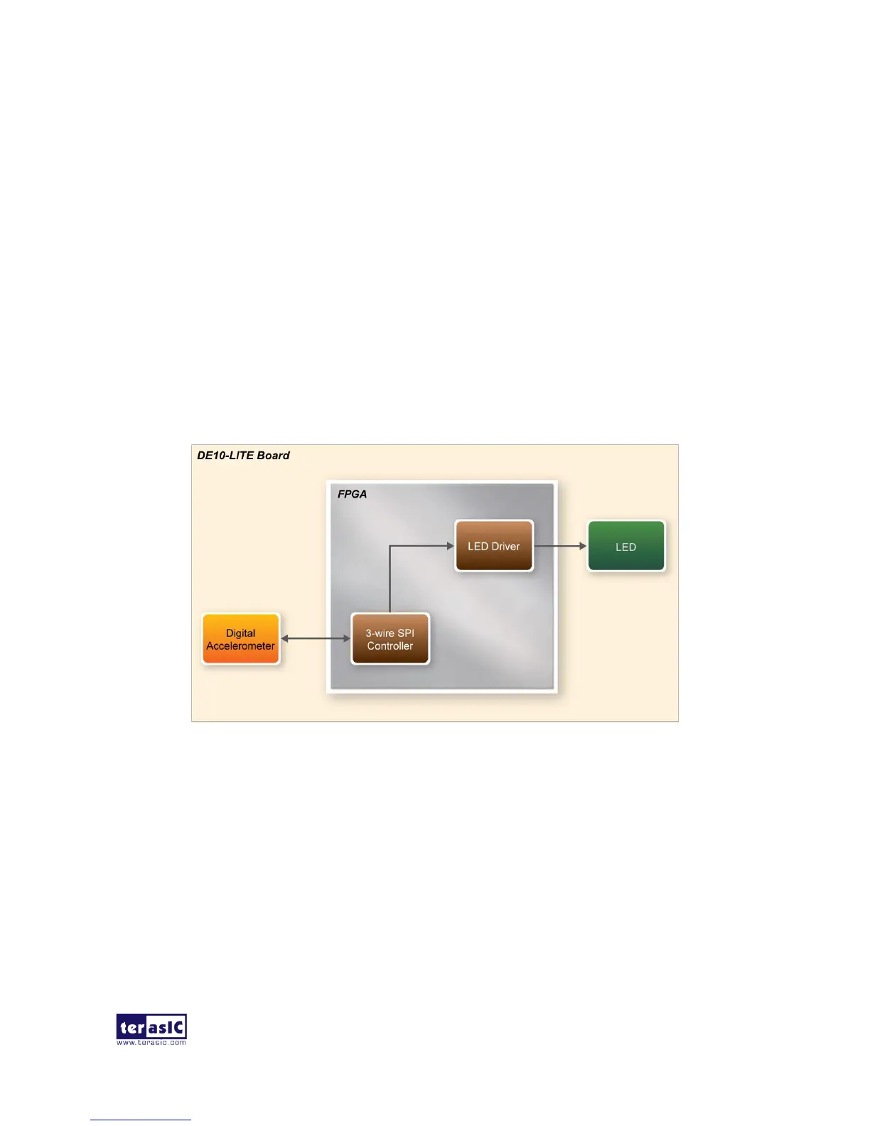
◼ Function Block Diagram
Figure 5-8 shows the system block diagram of this demonstration. In this system, the accelerometer
is controlled through a 3-wire SPI. Before reading any data from the accelerometer, the controller
sets 1 on the SPI bit in the Register 0x31 – DATA_FORMAT register. The 3-wire SPI Controller
block reads the digital accelerometer X-axis value, to determine the tilt of the board. The LEDs are
lit up as if they were a bubble, floating to the top of the board.
Figure 5-8 Block diagram of the G-Sensor
 Loading...